Background
I felt it was finally time to respin the board and bring this project to a proper close.
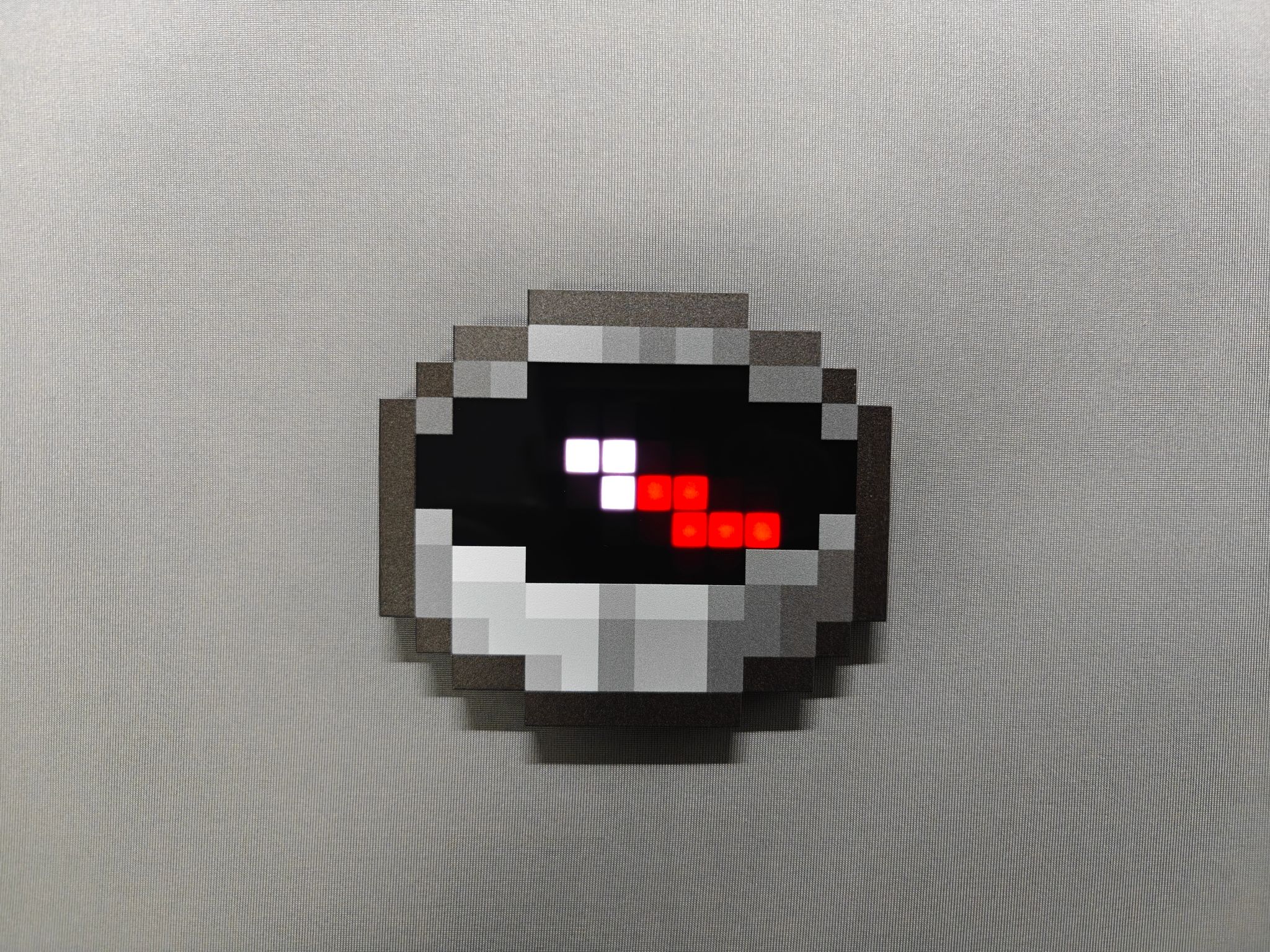
At the end of 2024, I released a Minecraft compass based on the ESP32-C3. That version could point to a specific real-world location, just like a Minecraft compass locked to a lodestone. It worked, but compared with the later simplified TiX version, it was more expensive and had much worse battery life.
At first, I even tried building a 4G version that could point devices toward each other. That meant 4G modules, server code, and a lot of extra complexity. In the end, it turned out to be a classic case of over-engineering: over-complicated, battery-draining, and offering zero practical value.
After that, I kept thinking about rebuilding the compass with cheaper hardware while keeping the core feature: pointing to a specific location. Once I left my job last year and had more time, I picked the project back up. But throughout the process, I kept asking myself whether I was just remaking something I had already made. Was it meaningful? Was I just repeating myself with no real innovation? So the project moved forward very, very slowly.
By the beginning of this year, the main functionality was basically done. Only a few small issues remained, but motivation was low. Realistically, the number of PCB revisions I ordered each month became the number of times I touched the project.
Then I started job hunting, and the project was shelved again. The assembled boards disappeared somewhere on my desk, and I could barely remember what I had changed or fixed in the previous revision.
During my first week back at the corporate grind, I looked at those half-finished boards collecting dust and suddenly felt it was time to respin the board, clean up the loose ends, and finally close the loop on this year-long obsession.
What Changed This Time
- The MCU has been downgraded from ESP32-C3 to the WCH CH592F.
- The ESP32-C3 module costs around 10 RMB (~
0.28 USD). - With the same LED brightness configuration, current draw dropped from about 100 mA to about 60 mA.
- USB is now available for both logging and online web-based configuration.
- The GPS module is soldered directly onto the PCB instead of being an optional add-on module.
- The power switch is much better. The old power switch was, quite frankly, notorious for being hard to use.
- The hardware is open-source. The firmware is not open-source, but activation codes are available for free.
- The LEDs have been improved for more even diffusion.
- Frosted LEDs are used for a cleaner and softer display effect.
Get Files
You can grab all the necessary files for free in my Ko-fi shop. If you would like to support my work and future iterations, feel free to leave a tip.
3D Model
I sold my 3D printer before moving and have not bought a new one yet, so I cannot currently verify or revise model-related issues myself.
Bill of Materials
This section only covers the battery, screws, and a few mechanical notes that are not listed in the interactive BOM.
Battery
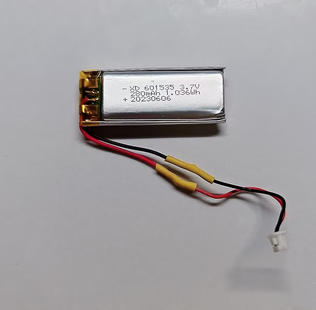
Use a 601535 Li-Po battery, 280 mAh. In theory, a 701435 battery with 330 mAh may also fit, but I have not verified it. The connector is 1.25 mm.
Screws
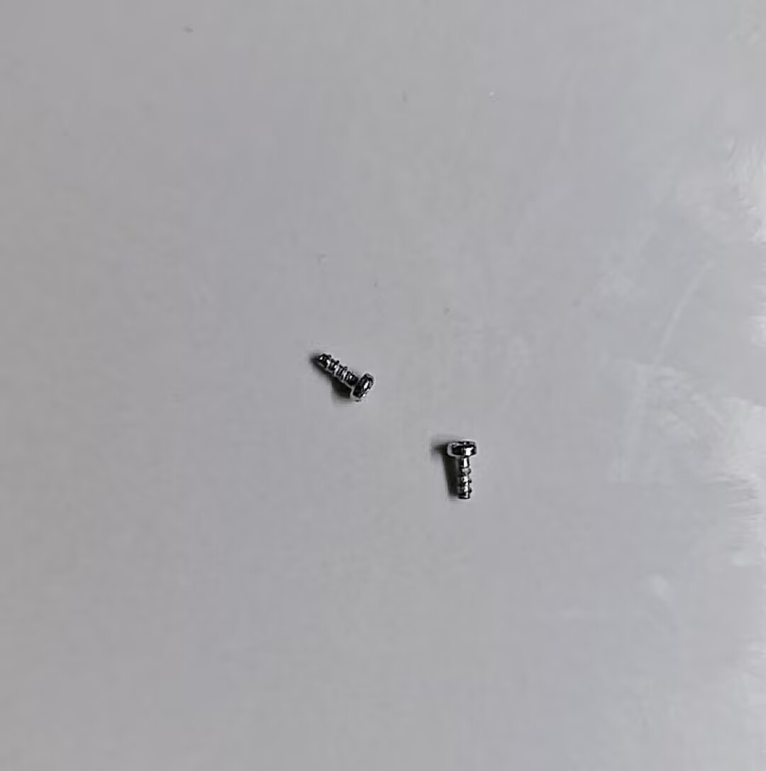
Use two Torx CB1.4 x 4 mm screws.
GPS Antenna
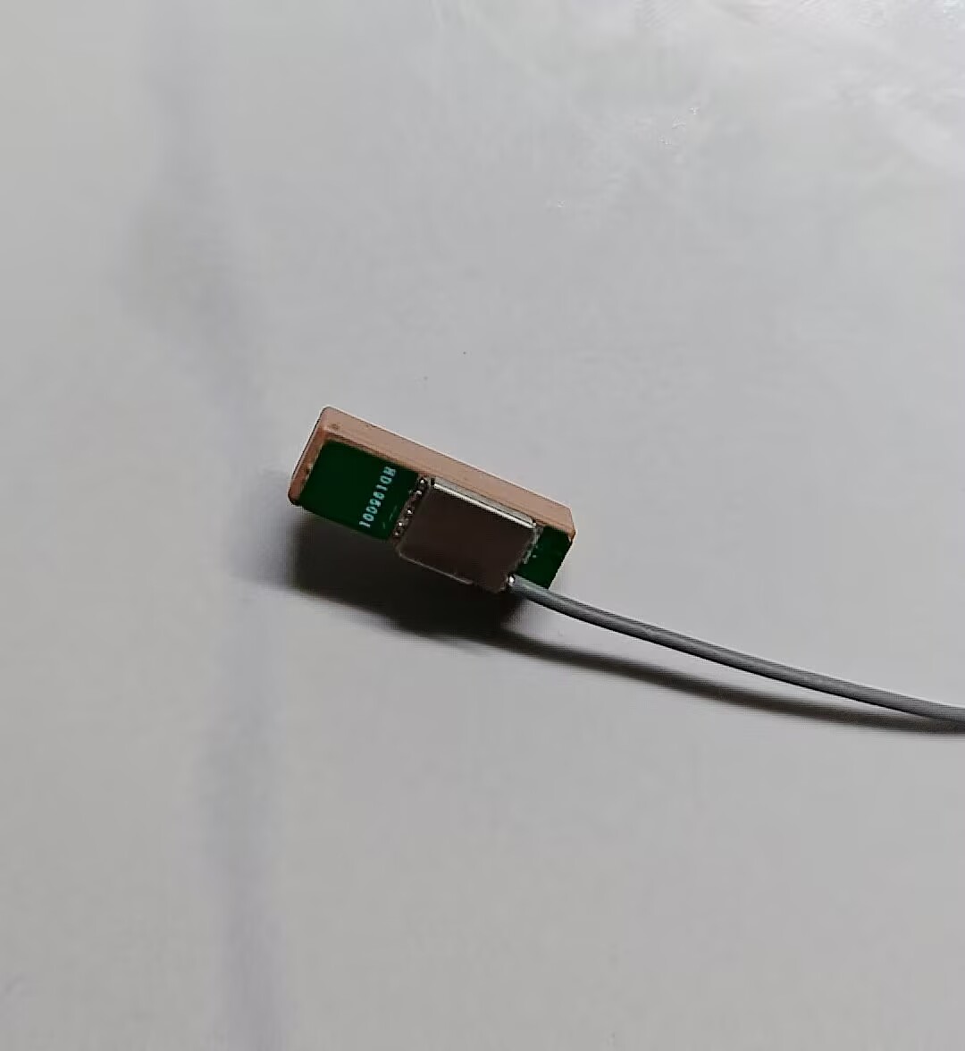
Choose an active ceramic GPS antenna with a 16 mm x 6 mm x 6 mm body. A 5 cm cable is enough.
Electronic Components
See the interactive BOM. The full component list is too long to be useful here.
Mechanical Parts
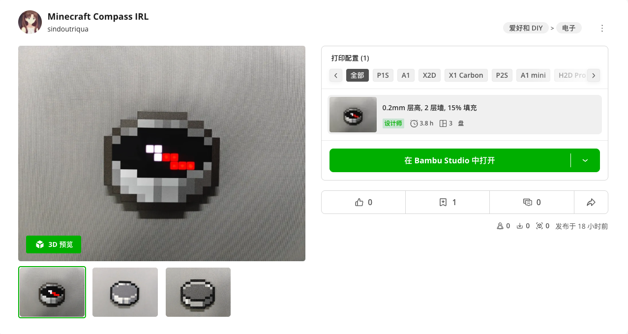
I uploaded the enclosure to MakerWorld. Choose the version you want to print: the acrylic-panel version or the multi-color printed version.
The multi-color version is not pre-colored, so you need to assign colors manually. The filament colors required for the multi-color version are listed on MakerWorld: white and black do not require special materials, dark gray is 10105, and light gray is 16101. Plate 3 contains a reference six-color scheme.
If you do not own a 3D printer, please use a reputable local printing service.
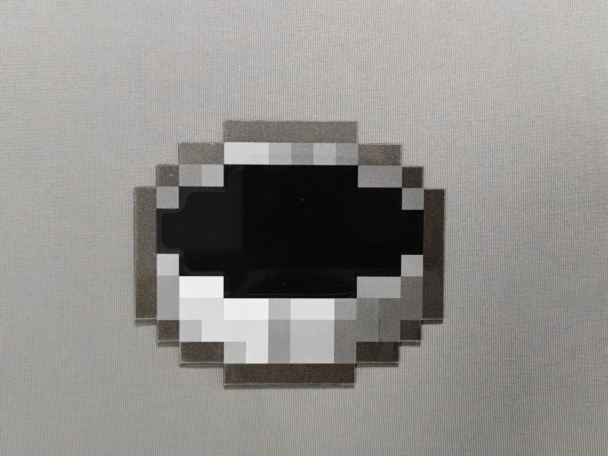
Panels
My personal favorite is the acrylic panel version. It gives a clearer and more evenly diffused display.
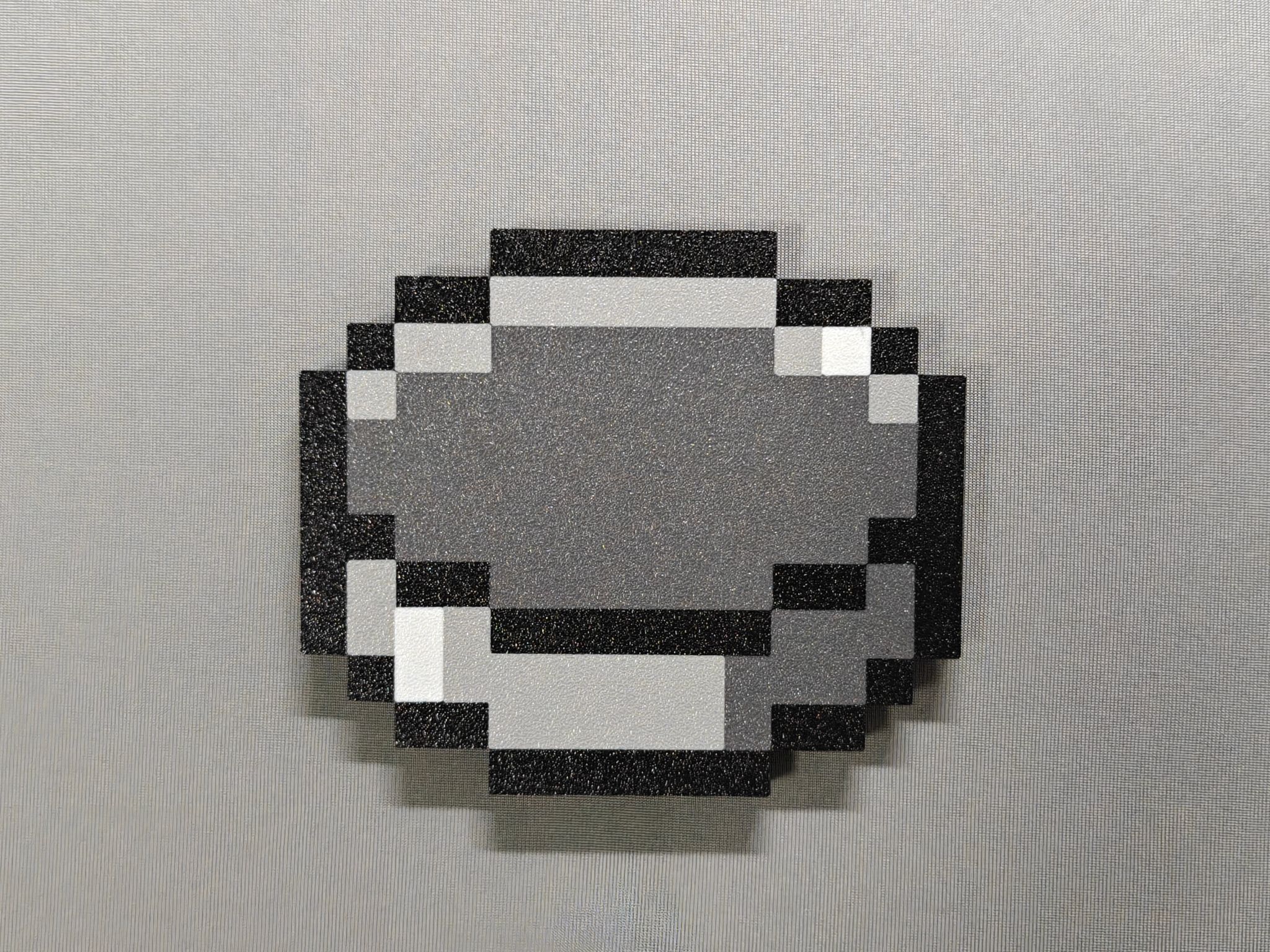
A TiX-like four-color version is also available.
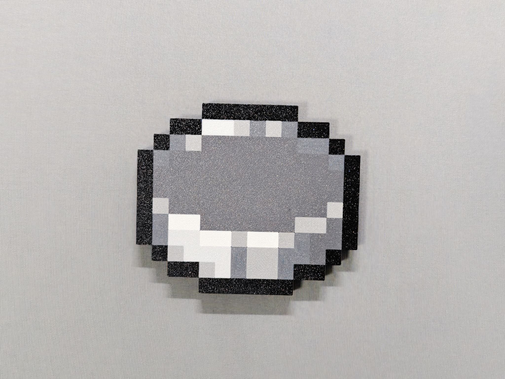
The six-color version is suitable if you have two AMS units. I tried many color combinations and bought quite a bit of filament, but still did not find a perfect result, so treat this one as a reference.
Additional Notes
For the acrylic panel, the parameters are:
- Thickness: 1 mm
- Material: black semi-transparent acrylic
- If ordering from JLCPCB, choose front-side printing
- No adhesive backing required
PET.dwg is the prepared PET film cutting file. You can also cut a piece manually with scissors if you prefer.
Build Guide
I strongly recommend ordering a solder paste stencil. This version is harder to solder than the previous one. I ordered a custom stencil for about 15 RMB (~$2 USD), and it was absolutely worth it. It can save you a lot of frustration and may even let you finish the soldering successfully on the first try.
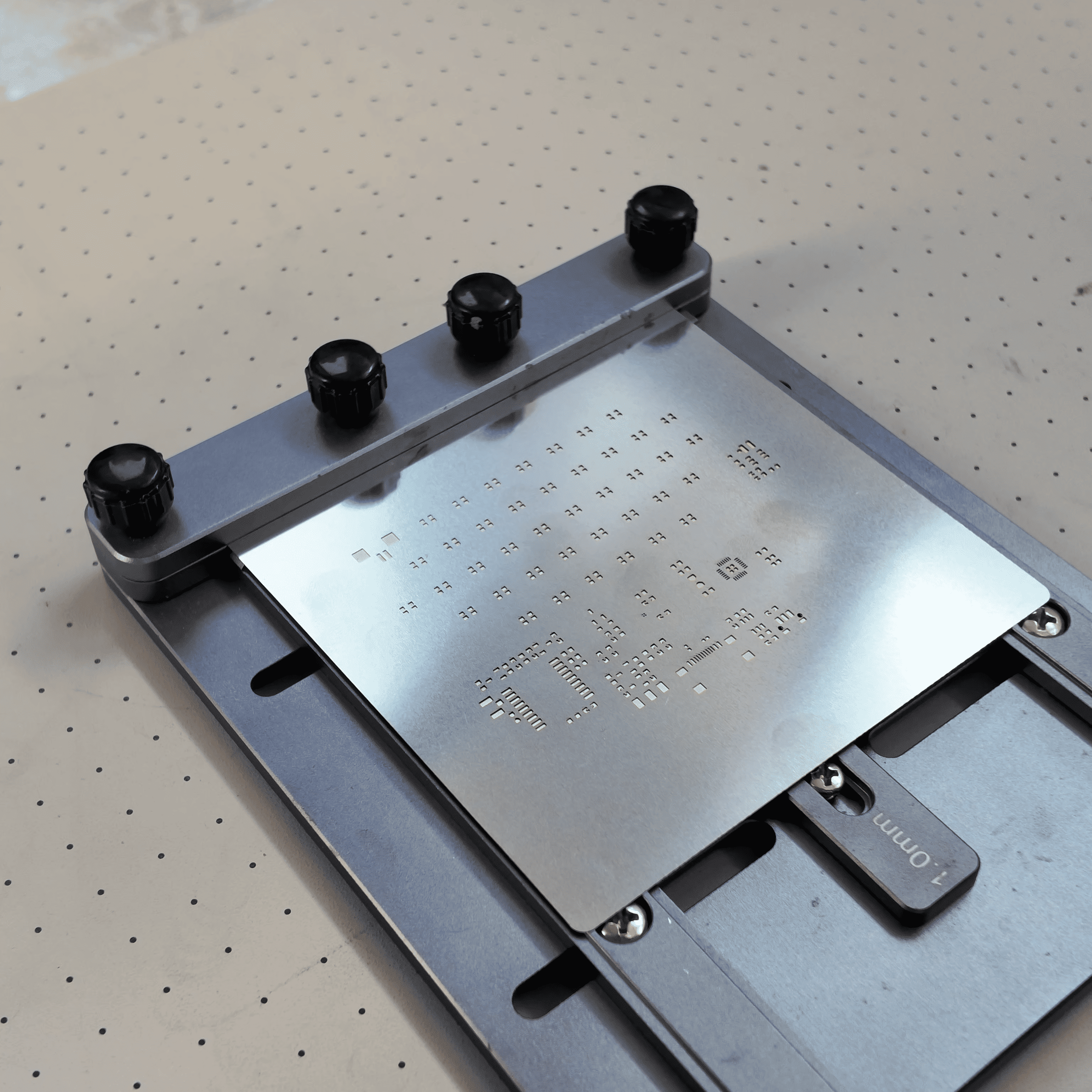
Soldering
Apply Solder Paste
Apply solder paste using the stencil.
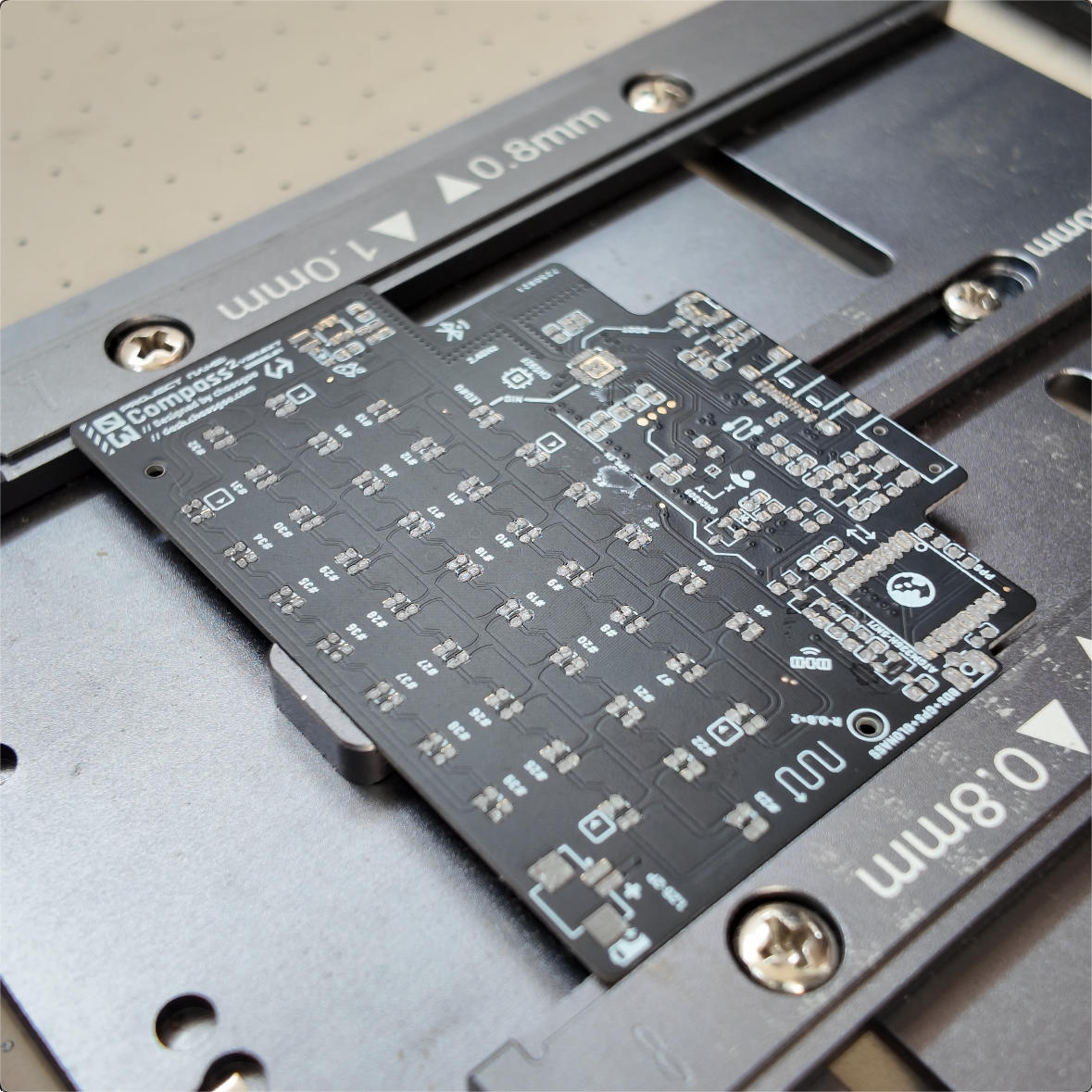
Place Components
Use the interactive BOM to place all components. Small offsets are acceptable because surface tension during reflow can pull components back into alignment.
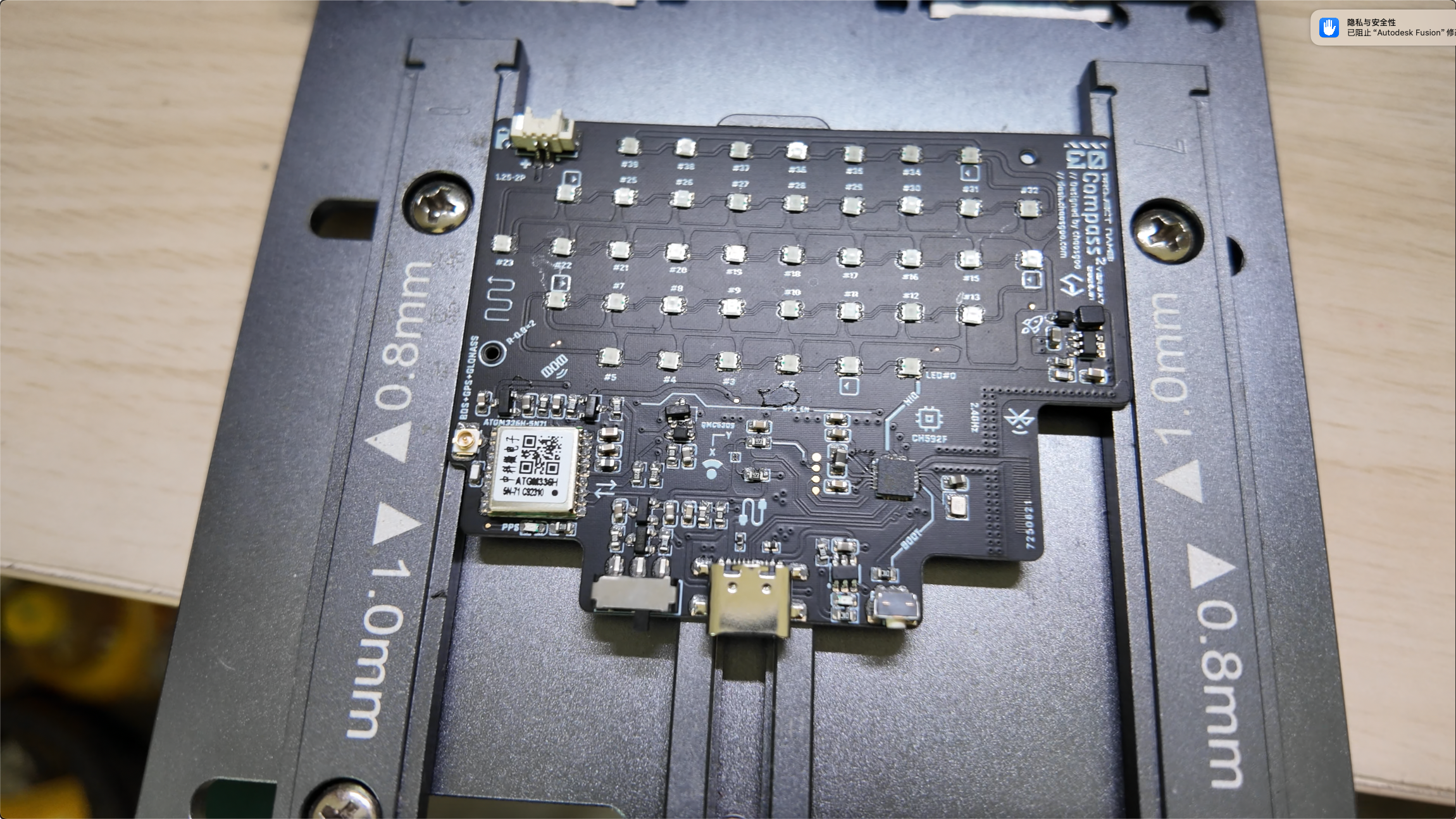
Double-check the orientation of the QMC6309 before applying flux. Once flux is on the chip, the marking becomes much harder to see.
Reflow
Place the board on a hot plate and reflow the solder paste. If surface tension is not enough to correct a shifted component, adjust it manually while reflowing.
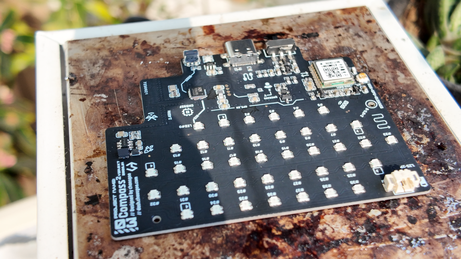
Clean the PCB (Optional but Recommended)
I recommend cleaning the PCB. Flux residue looks messy and may also affect the LED diffusion.
Make sure to work in a well-ventilated area and use proper protection.
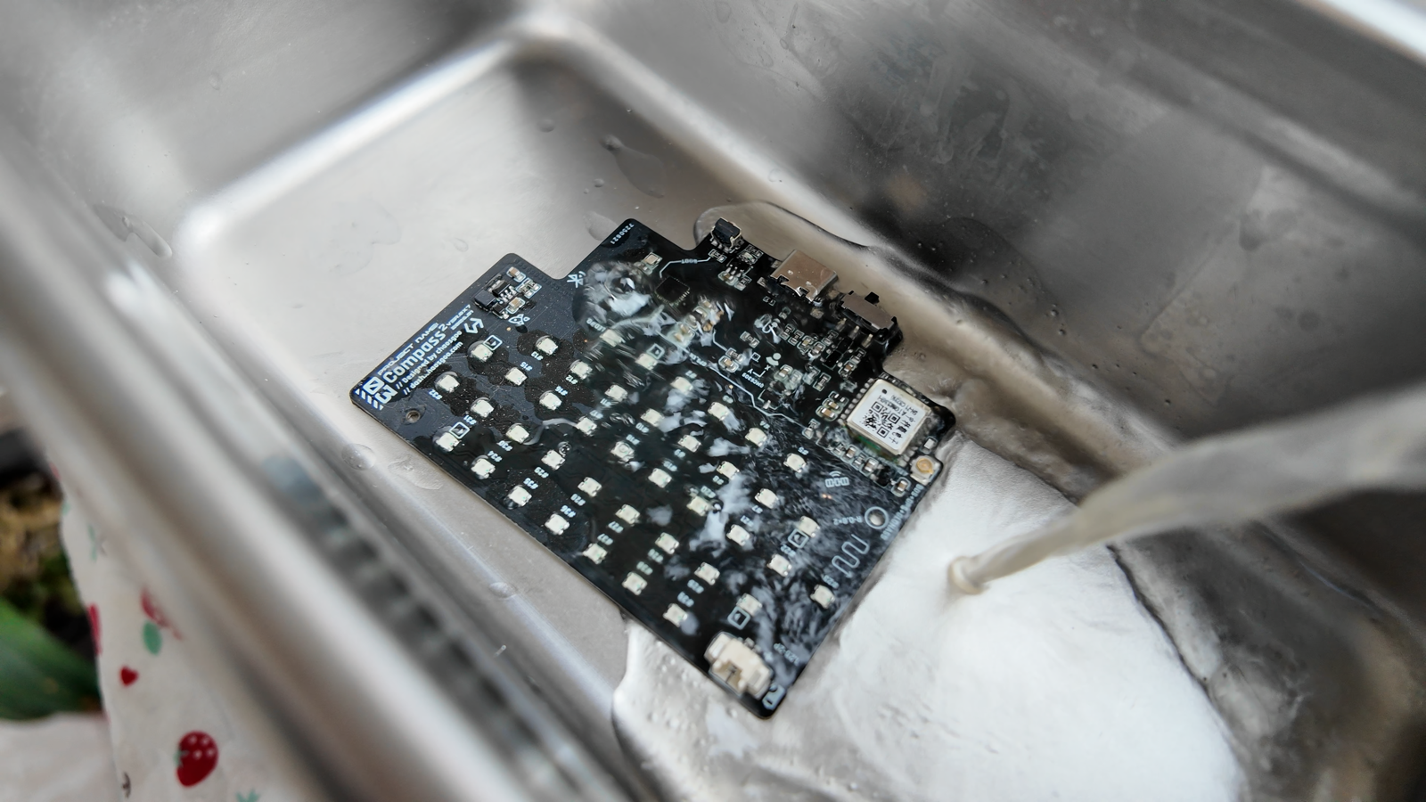
Soldering Inspection
Before powering the board, measure it with a multimeter. Check for cold joints, bridges, and shorts. If you plug the board into a computer while there is a short, the device may not respond, and in the worst case the short may damage your computer’s USB port.
After powering on, check that the LDO output is 3.3 V and the DCDC output is 5.0 V.
Flash Firmware
After inspection, connect the board to a computer and flash the firmware. The flashing tool is WCHISPTool, the official WCH programming utility.
Open the tool and set MCU Series to Low Power Bluetooth Series CH57x-CH59x.
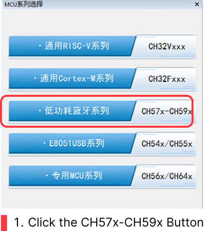
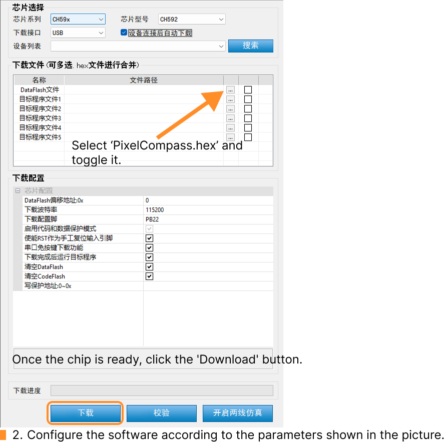
In the DataFlash tab, select the provided firmware file. Set the download interface to USB and enable automatic download after device connection.
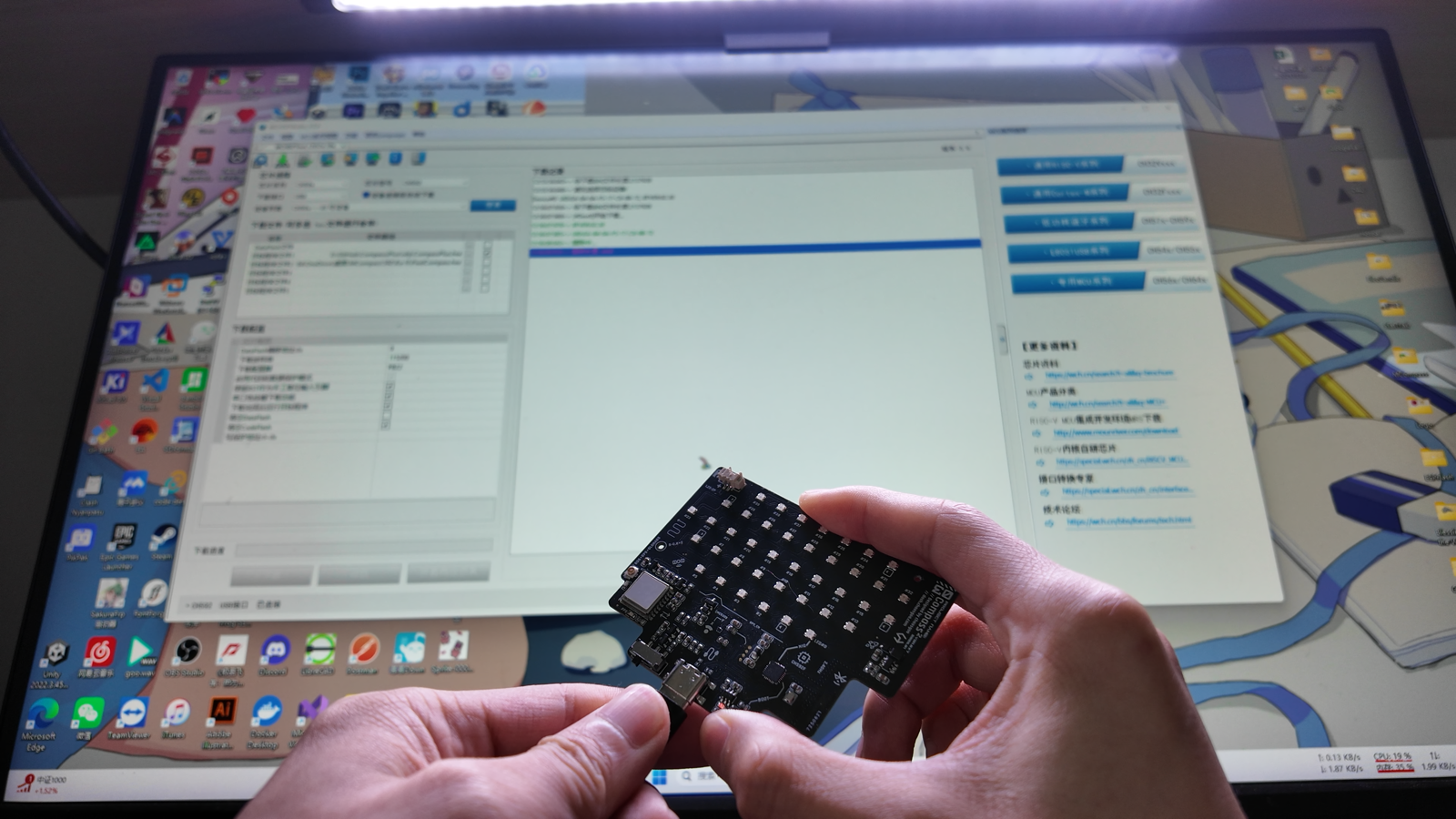
Move the left switch on the PCBA to the left. While holding the BOOT button on the right side, plug in the Type-C cable. Once the computer recognizes the device, the firmware should be flashed automatically.
If the device is not recognized or something else goes wrong, inspect the soldering again.
Activation
A Note on Open-Source Hardware & Firmware Activation
The hardware design is 100% open-source. However, based on the painful lessons of many great community DIY projects, early-stage designs are often instantly cloned by sketchy factories. They mass-produce them with cheap components and overcharge regular players without offering any tech support, which ultimately ruins the project’s reputation and community spirit.
To protect our early DIY ecosystem, the firmware source code is temporarily closed and requires a free activation code. Through this small checkpoint, I want to ensure that every early PixelCompass is built with care by a genuine maker. Once the project matures and stabilizes, I fully intend to publish the firmware source code on GitHub.
Get an activation code from my Ko-fi shop: PixelCompass Activation Code. After checkout, you will receive the activation code by email.
Open the PixelCompass dashboard and connect to the device. If the device is not activated, the dashboard will prompt you to enter the activation code from the email.
Set a Lodestone
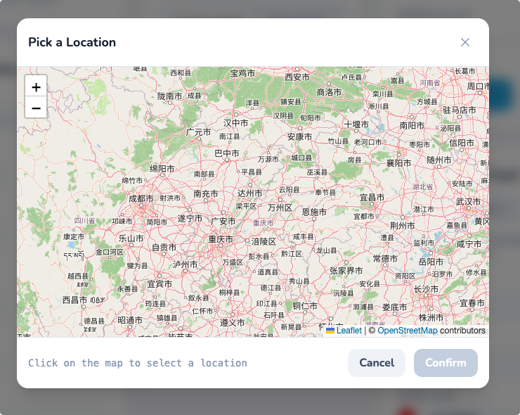
The dashboard provides an option to set a lodestone. You can select the target location directly on the map.
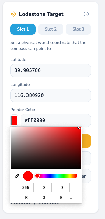
You can also customize which pointer color is used for that lodestone.
Assembly
I will use the acrylic version as the example.
First, place the PET film.
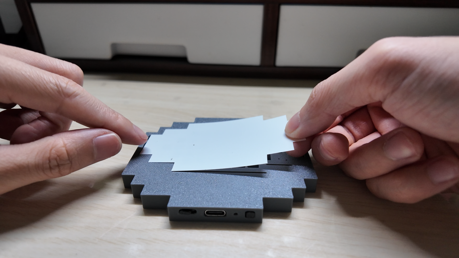
Do not forget to apply glue.
Then place the acrylic panel.
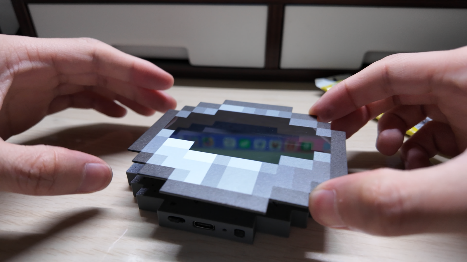
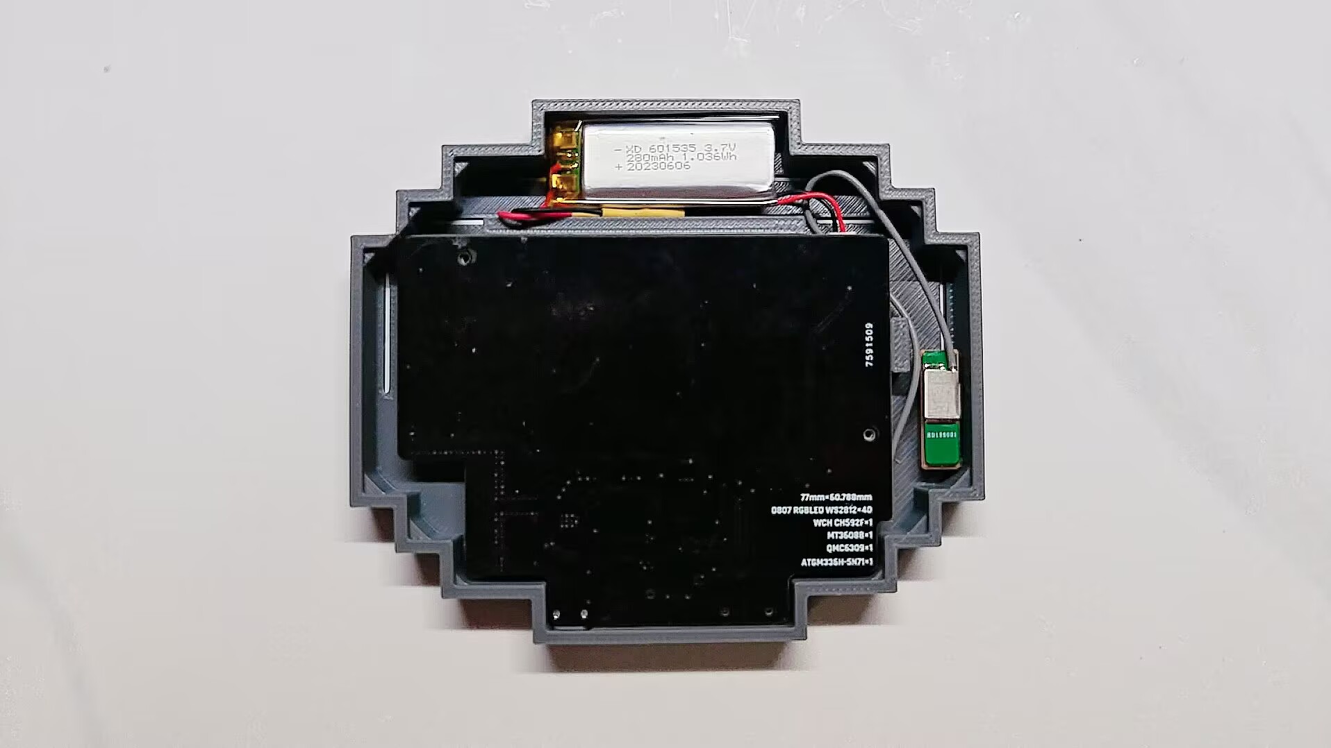
The back cover snaps on directly. Tighten the two screws and the enclosure is done.
During assembly, make sure the GPS antenna faces the front side of the compass. This way, when you hold the device, the antenna points toward the sky and can receive GPS signals more easily.
Done
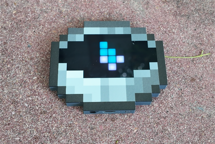
At this point, the device is complete.
Troubleshooting
Here are some common issues you may run into.
Nothing Happens When Plugging in USB After Soldering
- Check for shorts, opens, and solder bridges, especially around the CH592F and Type-C connector pins.
- Inspect the USB connector soldering. Also make sure your USB cable supports data transfer and is not charge-only.
- Check the CH592F soldering. My first time soldering the CH582F, a sister chip of the CH592F, took many attempts before the board was recognized.
- Check the crystal orientation. It is hard to identify, so confirm it carefully.
All LEDs Show White After Flashing
Check the QMC6309 soldering. If the geomagnetic sensor cannot be detected, the firmware will stay on this white screen.
Some LEDs Do Not Light Up After Flashing
Check the LED soldering. In this version, I marked the direction of every LED row, so confirm that orientation and soldering are both correct.
GPS Takes Too Long to Get a Fix
Confirm that the GPS module is soldered correctly. The dashboard can show the GPS status, which helps distinguish between MCU-GPS communication failure and antenna or signal issues.
GPS usually cannot get a fix indoors. Move to an open outdoor area.