Lenovo Savior R720 Keyboard Matrix Analysis and Transformation
preface
A friend asked me to help him convert his R720 laptop into KVM. Hence this article.
Keyboard introduction
Mainstream keyboards are basically matrix keyboards. This method saves IO. This R720 is no exception.
The R720 keyboard has a total of 96 keys. Using a matrix keyboard, theoretically (6+16=22) IOs are needed (actually it is quite a lot)
To avoid ghost key, the actual wiring is more complicated than ideal.
And compared to the direct lines of many DIY mechanical keyboards:
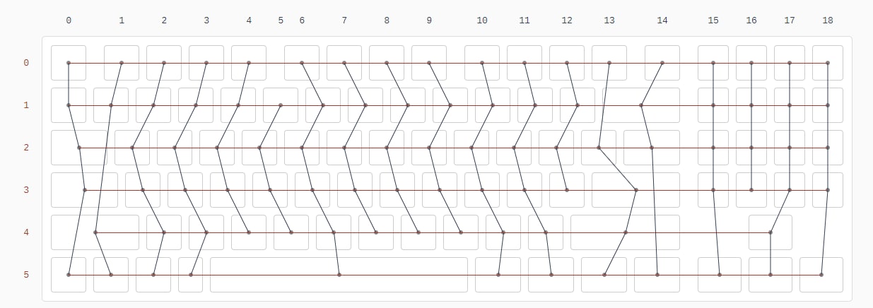 The internal wiring of the R720 keyboard seems very messy:
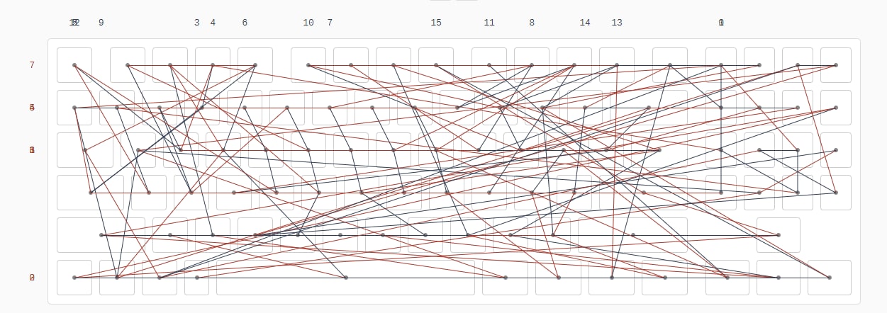 When I first got the test results, I always felt that I must have made a mistake. It was not until I found a notebook called Framework Laptop with a similar KeyMap that I felt relieved.
KeyMap mapping
I found an article Articles teaching people how to convert their laptops to KVM, which mentioned matrix keyboard driver control module Monkey. When I saw it, it was similar to the ATMEGA32U4. It should be a product of the same series. It sold for 50 on Taobao. Wouldn’t this kill me? Since the price increase of microcontrollers last year, Atmel’s products have not returned to their previous prices. I feel that if I buy them now, I would be a complete injustice. Moreover, you can make a similar thing by yourself. At that time, the only board with so many IOs was a Raspberry Pi Pico, and QMK also supported Pico, so I first used Pico to map the KeyMap. Get the following results
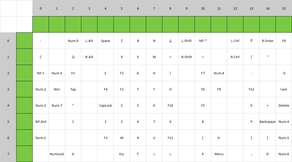
You ask me how I know the Row Pin and Col Pin. Isn’t it a coincidence? I found the schematic diagram of a notebook with the same mold on Google (website).
By the way, I also know the touchpad pin definition, and then directly enable QMK’s PS/2 mouse support and drive the touchpad together.
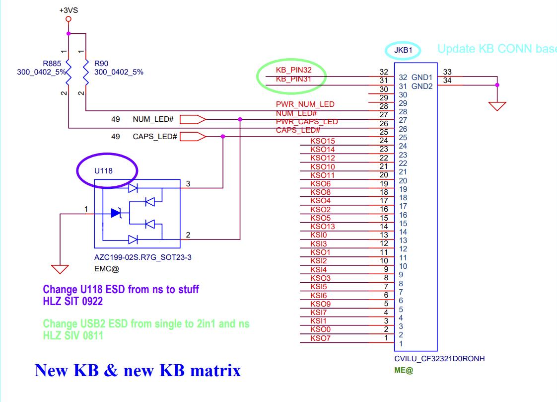
Schematic
After getting the Key Map, you can start drawing the board. Due to the inability to use Pico to compile firmware that supports PS/2 Mouse, the main control was replaced by the common ATMEGA32U4. After changing the main control, IO starts to be in short supply, but it doesn’t matter. You can use a chip to expand IO to cope with this situation. After taking a look at the solutions in the QMK warehouse, most of them use output IO expansion to solve the problem. Unfortunately, the scanning direction of this keyboard is opposite to that of a regular keyboard, so if nothing else, I will have an accident. So I bought a 74HC595 to expand the output IO and it worked perfectly. After rechecking, I realized that I had to use a 74HC165 to expand the input IO.
After procrastinating for a long time and encountering many pitfalls such as PS/2 Mouse having to use a specified IO driver, I finally drew the following solution using the 74HC165 schematic (it is a shame to waste so many free boarding opportunities from JLC.)
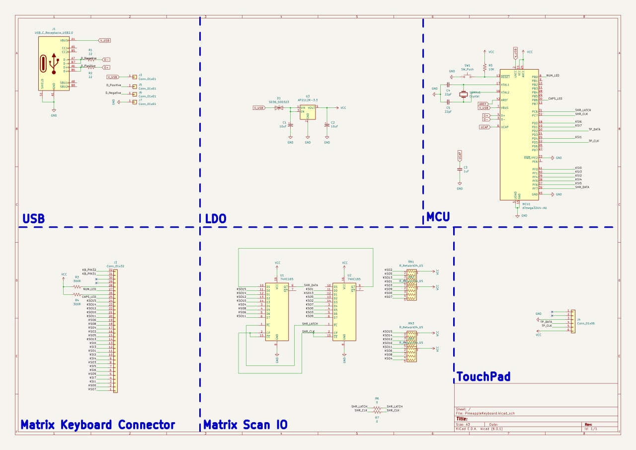
QMK Pin Map
Refer to the Key Map mapped out, and then use web tools to obtain the Key Map required for the final QMK firmware. In order to make the multimedia keys work properly, a two-layer Key Map is set up.
const uint16_t PROGMEM keymaps[][MATRIX_ROWS][MATRIX_COLS] = {
    LAYOUT_pa(
		KC_PMNS, KC_PSLS, KC_P0, KC_LALT, KC_SPC, KC_Z, KC_B, KC_N, KC_DOWN, KC_LSFT, KC_PAST, KC_LCTL, KC_UP, KC_ENT, KC_F8,
		KC_C, KC_Q, KC_RALT, KC_X, KC_V, KC_M, KC_DOT, KC_RSFT, KC_COMM, KC_RCTL, KC_SLSH, KC_QUOT,
		KC_PPLS, KC_P9, MO(1), KC_E, KC_F2, KC_G, KC_H, KC_BSLS, KC_F7, KC_P8, KC_MINS, KC_RGHT,
		KC_P2, KC_LGUI, KC_TAB, KC_F4, KC_F1, KC_T, KC_Y, KC_O, KC_F6, KC_F9, KC_F12, KC_PSLS,
		KC_P3, KC_P7, KC_GRV, KC_CAPS, KC_S, KC_5, KC_6, KC_F10, KC_F5, KC_0, KC_EQL, KC_DEL,
		KC_PDOT, KC_1, KC_3, KC_2, KC_4, KC_7, KC_9, KC_8, KC_P, KC_BSPC, KC_P4,
		KC_P1, KC_F3, KC_W, KC_R, KC_U, KC_F11, KC_I, KC_LEFT, KC_LBRC, KC_RBRC, KC_P5,
		KC_NUM, KC_A, KC_ESC, KC_F, KC_J, KC_L, KC_K, KC_APP, KC_SCLN, KC_D, KC_P6),

	LAYOUT_pa(
		KC_PAUS, KC_MNXT, KC_TRNS, KC_TRNS, KC_TRNS, KC_TRNS, KC_TRNS, KC_TRNS, KC_PGDN, KC_TRNS, KC_TRNS, KC_TRNS, KC_PGUP, KC_TRNS, KC_TRNS,
		KC_TRNS, KC_TRNS, KC_TRNS, KC_TRNS, KC_TRNS, KC_TRNS, KC_TRNS, KC_TRNS, KC_TRNS, KC_TRNS, KC_TRNS, KC_TRNS,
		KC_TRNS, KC_MPRV, KC_TRNS, KC_TRNS, KC_VOLD, KC_TRNS, KC_TRNS, KC_TRNS, KC_TRNS, KC_MPLY, KC_TRNS, KC_END,
		KC_PSCR, KC_TRNS, KC_TRNS, KC_TRNS, KC_MUTE, KC_TRNS, KC_TRNS, KC_TRNS, KC_TRNS, KC_TRNS, KC_TRNS, KC_TRNS,
		KC_TRNS, KC_TRNS, KC_TRNS, KC_TRNS, KC_TRNS, KC_TRNS, KC_TRNS, KC_TRNS, KC_TRNS, KC_TRNS, KC_TRNS, KC_TRNS,
		KC_DEL, KC_TRNS, KC_TRNS, KC_TRNS, KC_TRNS, KC_TRNS, KC_TRNS, KC_TRNS, KC_TRNS, KC_TRNS, KC_TRNS,
		KC_INS, KC_VOLU, KC_TRNS, KC_TRNS, KC_TRNS, KC_TRNS, KC_TRNS, KC_HOME, KC_TRNS, KC_TRNS, KC_TRNS,
		KC_TRNS, KC_TRNS, KC_TRNS, KC_TRNS, KC_TRNS, KC_TRNS, KC_TRNS, KC_TRNS, KC_TRNS, KC_TRNS, KC_TRNS),
};
physical object
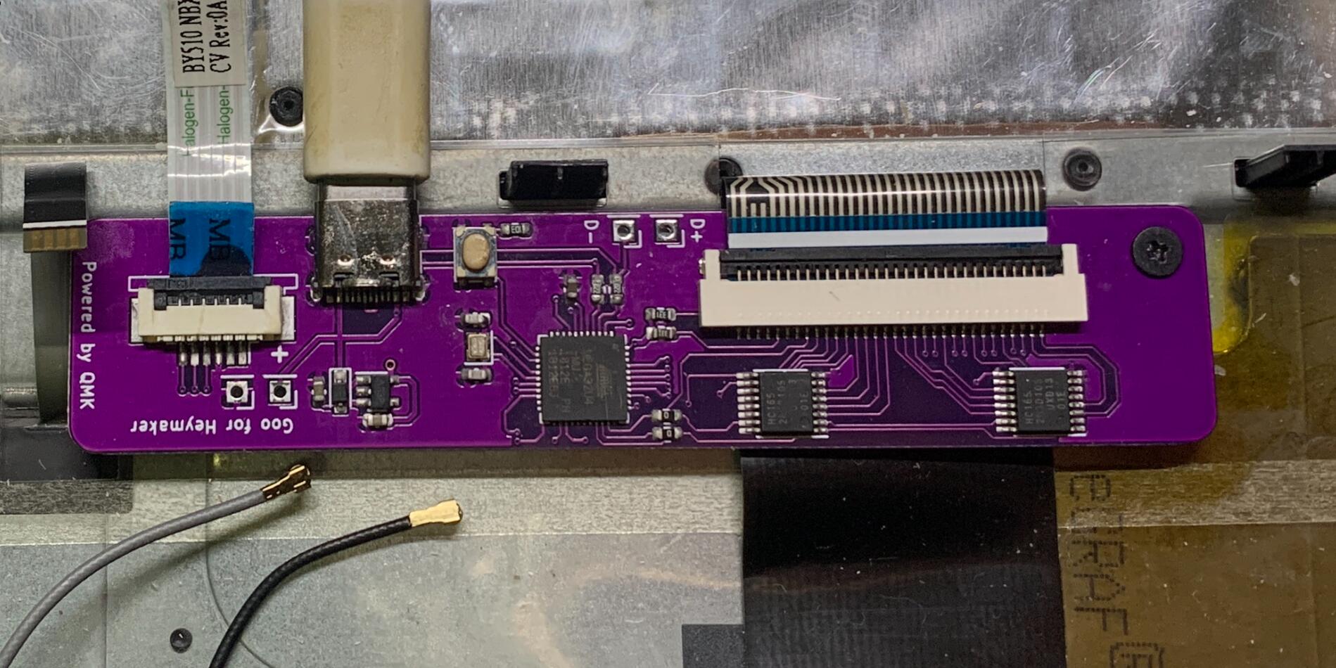
Regret
The voltage of the backlight is 5V, but I haven’t adapted it. I’m past the age where I like backlights.
More
I also downloaded the one called BoardView on the laptop motherboard, and then I converted (measured, and then manually drew) it to get the DWG diagram. Once you know the exact hole opening, it will be easier to fix it by drawing the board.
References
Transform an old laptop into a portable KVM Framework Laptop Key Matrix QMK Firmware Laptop Bios & Schematics