Preface
The house I live in has no socket near the bed and no switch to control the ceiling light in the room. If I turn off the lights and go to bed, the room will be plunged into darkness.
So for a long time, I kept the controller of the Mijia monitor light bar on the bedside for temporary lighting.
This leads to another problem. Every time I go home and turn on the computer to turn on the monitor light bar, I have to go to the bedside to find the controller to turn on the monitor light bar.

After going through many troubles, I decided to connect this monitor light bar to HomeKit. This way it can be controlled by voice or mobile phone.
Data collection
After reading this article Disassembly report: MJ Mijia display hanging lamp MJGJD01YL, the work that needs to be done is clear. It can be roughly divided into the following steps:
- Read the manual and find the control pins
- Remove the chip and replace it with ESP32
- Write code and connect to HomeKit
Read the manual and find the control pins
After reading the disassembly report, I learned that the brightness is controlled by TLSR8368 and SY7301A chips. Information about these two chips can be easily found on Google.
Basically, it can be determined that the TLSR8368 sends the PWM signal to the SY7301A for dimming.
TLSR8368 has a total of 16 pins. According to the manual and using an oscilloscope to measure the control pins one by one, it is found that the PWM pins are generated by #3 and #5, and there is also a pin #8 used to enable the SY7301A chip.

The measured pins are as follows
Remove the chip and replace it with ESP32
At this step, you need to select a chip of appropriate size, and then redraw a board to parasitize it in the original position.
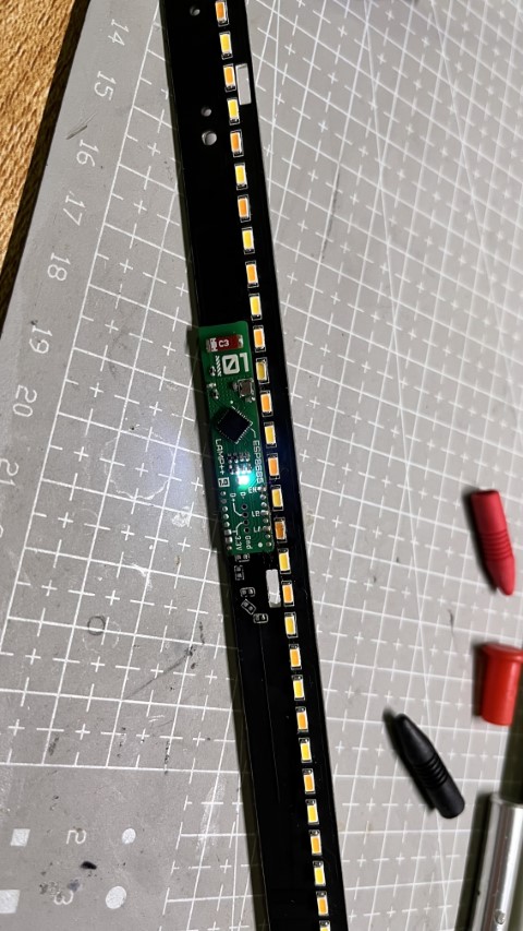
The pad space of TLSR8368 is quite spacious. You can solder an ESP32-C3 with a smaller package (the corresponding model name is ESP8685), and the package is QFN28 4x4mm.

The TypeC and LDO parts on the right half here will be broken after flashing, and subsequent firmware can be updated through 4P 2mm pitch probe or OTA.
Attached is a picture of the first version after soldering. The first version was a version that did not have the breakable TypeC part.
Write code and connect to HomeKit
Thanks to the HomeSpan library, the code that needs to be written is very simple.
At present, the dimming of white LEDs has been realized. Because I damaged the solder resist of the warm yellow LED control pin, the final version failed to realize the color temperature adjustment function.
Therefore, the following code mainly demonstrates how to control the switching and dimming of white LEDs
##include <Arduino.h>

##include "HomeSpan.h"
##include "extras/PwmPin.h"  // library of various PWM functions

////////////////////////////////////

struct FadingLED : Service::LightBulb {
  LedPin *ledPin;             // reference to Led Pin
  SpanCharacteristic *power;  // reference to the On Characteristic
  SpanCharacteristic *level;  // reference to the Brightness Characteristic
  SpanCharacteristic *colorTemperature;  // reference to the Color Temperature

  FadingLED(int _ledPin) : Service::LightBulb() {
    power = new Characteristic::On();
    level = new Characteristic::Brightness(0);
    colorTemperature = new Characteristic::ColorTemperature(200, true);
    ledPin = new LedPin(_ledPin);
  }

  boolean update() {
    Serial.printf("power->getNewVal()=%d", power->getNewVal());
    Serial.printf(",level->getNewVal()=%d", level->getNewVal());
    Serial.printf(",colorTemperature->getNewVal()=%d\n",
                  colorTemperature->getNewVal());
    ledPin->fade(power->getNewVal() * level->getNewVal(), 2000,
                 LedPin::PROPORTIONAL);
    while (ledPin->fadeStatus() == LedPin::FADING)
      ;

    return (true);
  }

  void loop() override {
    if (ledPin->fadeStatus() == LedPin::COMPLETED) {
      power->setVal(1 - power->getVal());
      level->setVal(power->getVal() ? 100 : 0);
    }
  }
};

//////////////////////////////////

void setup() {
  pinMode(5, OUTPUT);
  pinMode(10, OUTPUT);
  digitalWrite(5, HIGH);
  digitalWrite(10, LOW);
  Serial.begin(115200);
  digitalWrite(10, HIGH);

  Serial.println("Wi-Fi is Connected!");
  homeSpan.enableOTA("12345678");
  homeSpan.setPairingCode("11223344");
  homeSpan.begin(Category::Lighting, "Lamp++");

  new SpanAccessory();
  new Service::AccessoryInformation();
  new Characteristic::Identify();
  new Characteristic::ColorTemperature(200, true);
  new FadingLED(4);
}

//////////////////////////////////////

void loop() {
  homeSpan.poll();
}
[env:airm2m_core_esp32c3]
platform = espressif32@5.4.0
board = airm2m_core_esp32c3
framework = arduino
monitor_speed = 115200
lib_deps = homespan/HomeSpan@^1.8.0
; upload_protocol = espota
; upload_flags =  --auth=12345678
; upload_port = 192.168.0.104
build_flags =
	-D ARDUINO_USB_MODE=1
	-D ARDUINO_USB_CDC_ON_BOOT=1
Effect display