background
I participated in the fourth phase of FastBond last year. In order to get this development board for free, I had to take out this board to complete a project before the deadline. After reading the activity requirements, I feel that lighting lanterns is the easiest. But since you have already lit lanterns, let’s light something a little more difficult. For example, lighting up the WS2812 RGB LED can increase performance by 200%.
Development board introduction
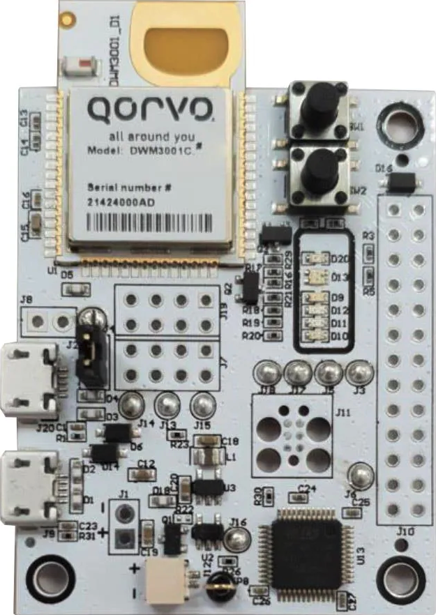
- There is a DWM3001C module on the board
- Interoperable with Apple U1 chip & U2
- Support UWB channels 5 (6.5 GHz) and 9 (8 GHz)
- Onboard J-Link for debugging and programming
- USB interface for direct connection to DWM3001C USB interface
- 26 pin Raspberry Pi compatible interface
- With reset and a user button, onboard LED
- All DWM3001C GPIOs and interfaces are pinned out
DWM3001C has an nRF52833 chip inside, and the actual code actually runs on this chip. The development tools are also based on the nRF52833 SDK.
Control common LEDs
nRF’s documentation and information are very complete. Not only are there examples of lights, but the pin definitions of the board’s LEDs and Buttons are also predefined.
Without further ado, let’s just open the official example and take a look. Although I have never been exposed to nRF’s SDK before, based on my previous ESP development experience, it is not difficult to understand the sample code.
When the sample project is started, you will see that the four onboard LEDs will flash. Check the startup code to see that the actual code is
void BoardInit(void)
{
    bsp_board_init(BSP_INIT_LEDS | BSP_INIT_BUTTONS);
    peripherals_init();

    for (int i = 0; i < 6; i++)
    {
        bsp_board_led_invert(BSP_BOARD_LED_0);
        bsp_board_led_invert(BSP_BOARD_LED_1);
        bsp_board_led_invert(BSP_BOARD_LED_2);
        bsp_board_led_invert(BSP_BOARD_LED_3);
        nrf_delay_ms(250);
    }
}
Even the LED control is thoughtfully packaged, bsp_board_led_on and bsp_board_led_off,
At the same time, I also saw the code that flashes the LED when the serial port is refreshed.
static void logger_thread(void *arg) {
    UNUSED_PARAMETER(arg);

    while (1) {
        NRF_LOG_FLUSH();
        bsp_board_led_on(BSP_BOARD_LED_1);
        nrf_delay_ms(1);
        bsp_board_led_off(BSP_BOARD_LED_1);
        nrf_delay_ms(1);
        vTaskSuspend(NULL); // Suspend myself
    }
}
Writing a driver for WS2812
There are many ways to drive WS2812, choose the most appropriate driving method according to the situation.
IO simulation (Bit-Banging)
This is the most classic method. If the chip is relatively simple and does not have an SPI interface, or the SPI interface is occupied, you can consider using IO simulation. The disadvantage is that it consumes CPU resources. Arduino Uno drives WS2812 in this way 1.
PWM + DMA simulation
This method is equivalent to an optimized version of IO simulation. After the introduction of DMA, the pressure on CPU resources is released.
SPI simulation
This is a way to save the country by using the SPI sending mechanism to simulate the WS2812 protocol, which is suitable for scenarios where the SPI interface is idle. When combined with SPI DMA, almost no CPU resources are consumed.
RMT simulation
This is the driving method of the ESP32 chip, which uses RMT peripherals to simulate the WS2812 protocol. It is the most elegant, the simulation timing is very accurate, and does not require CPU intervention.2.
final choice
Considering the difficulty of implementation and the actual effect, I decided to use SPI simulation to implement the driver simulation of WS2812 on DWM3001CDK.
Driver writing
Refer to https://www.cnblogs.com/milton/p/17892606.html, to modify the spi driver to nrf52833 version. Write initialization SPI code
void ws2812_init(void) {
  nrf_gpio_cfg_output(30);
  nrf_gpio_cfg_output(27);
  nrf_gpio_cfg_output(31);
  memset(ws2812_buffer, 0, WS2812_BUFFER_SIZE);
  nrf_drv_spi_config_t spi_config = NRF_DRV_SPI_DEFAULT_CONFIG;
  spi_config.ss_pin               = NRF_GPIO_PIN_MAP(0, 30);
  spi_config.miso_pin             = NRF_DRV_SPI_PIN_NOT_USED;
  spi_config.mosi_pin             = NRF_GPIO_PIN_MAP(0, 27);
  spi_config.sck_pin              = NRF_GPIO_PIN_MAP(0, 31);
  spi_config.frequency            = NRF_DRV_SPI_FREQ_4M;
  spi_config.mode                 = NRF_DRV_SPI_MODE_0;    // SPI 模式 0
  int spi_ret                     = nrf_drv_spi_init(&spi, &spi_config, spi_event_handler, NULL);
  NRF_LOG_ERROR("ws2812_init() = %d", spi_ret);
}
Write the sending function code
  NRF_LOG_INFO("ws2812_send_spi()");

  APP_ERROR_CHECK(nrf_drv_spi_transfer(&spi, ws2812_buffer, WS2812_BUFFER_SIZE, NULL, 0));
  while (!spi_xfer_done) {
    __WFE();
  }
  // 发送复位信号(保持 MOSI 低电平至少 50µs)
  nrf_gpio_pin_clear(NRF_GPIO_PIN_MAP(0, 27));
  nrf_delay_us(50);
It is necessary to modify the nrf_drv_spi_transfer statement and definition, and change the third parameter to size_t type. Otherwise, data of the size of WS2812_BUFFER_SIZE cannot be transmitted at one time, resulting in abnormal color.
Write a color setting function and add a color conversion function.
void ws2812_pixel(uint16_t led_no, uint8_t r, uint8_t g, uint8_t b) {
  uint8_t *ptr = &ws2812_buffer[led_no * 24];
  WS2812_FILL_BUFFER(g);
  WS2812_FILL_BUFFER(r);
  WS2812_FILL_BUFFER(b);
}

void ws2812_pixel_all(uint8_t r, uint8_t g, uint8_t b) {
  uint8_t *ptr = ws2812_buffer;
  for (uint16_t i = 0; i < WS2812_NUM_LEDS; ++i) {
    WS2812_FILL_BUFFER(g);
    WS2812_FILL_BUFFER(r);
    WS2812_FILL_BUFFER(b);
  }
}

void hsv_to_rgb(uint8_t h, uint8_t s, uint8_t v, uint8_t *r, uint8_t *g, uint8_t *b) {
  uint8_t region, remainder, p, q, t;

  if (s == 0) {
    *r = v;
    *g = v;
    *b = v;
    return;
  }

  region    = h / 43;
  remainder = (h - (region * 43)) * 6;

  p = (v * (255 - s)) >> 8;
  q = (v * (255 - ((s * remainder) >> 8))) >> 8;
  t = (v * (255 - ((s * (255 - remainder)) >> 8))) >> 8;

  switch (region) {
  case 0:
    *r = v;
    *g = t;
    *b = p;
    break;
  case 1:
    *r = q;
    *g = v;
    *b = p;
    break;
  case 2:
    *r = p;
    *g = v;
    *b = t;
    break;
  case 3:
    *r = p;
    *g = q;
    *b = v;
    break;
  case 4:
    *r = t;
    *g = p;
    *b = v;
    break;
  default:
    *r = v;
    *g = p;
    *b = q;
    break;
  }
}
Finally, add the classic gradient function
void ws2812_row_gradient(uint16_t i) {
  for (uint8_t row = 0; row < WS2812_ROWS; row++) {
    for (uint8_t col = 0; col < WS2812_COLS; col++) {
      // 计算当前 LED 的色相值
      uint8_t hue = (i + row * 256 / WS2812_ROWS) % 256;
      uint8_t r, g, b;

      // 将 HSV 转换为 RGB,亮度设置为 50
      hsv_to_rgb(hue, 255, 16, &r, &g, &b);

      // 计算 LED 索引
      uint16_t led = row * WS2812_COLS + col;

      // 设置 LED 颜色
      ws2812_pixel(led, r, g, b);
    }
  }
}

void ws2812_col_gradient(uint16_t i) {
  for (uint8_t col = 0; col < WS2812_COLS; col++) {
    for (uint8_t row = 0; row < WS2812_ROWS; row++) {
      // 计算当前 LED 的色相值
      uint8_t hue = (i + col * 256 / WS2812_COLS) % 256;
      uint8_t r, g, b;

      // 将 HSV 转换为 RGB,亮度设置为 50
      hsv_to_rgb(hue, 255, 50, &r, &g, &b);

      // 计算 LED 索引
      uint16_t led = row * WS2812_COLS + col;

      // 设置 LED 颜色
      ws2812_pixel(led, r, g, b);
    }
  }
}
The first LEDs color abnormality fix
After the above code is written and burned, it is found that the first LEDs are always green. After some searching, I found a fix. The core idea is to send a few zero bytes before sending data.3
So we add header zero bytes to the buffer
#define WS2812_NUM_LEDS 60      // 6x10 灯板,共 60 个 LED
#define WS2812_RESET_PULSE 60
#define WS2812_EXTRA_ZEROS 4    // 添加 4 个零字节
#define WS2812_BUFFER_SIZE (WS2812_NUM_LEDS * 24 + WS2812_RESET_PULSE + WS2812_EXTRA_ZEROS)
Also update the initialization code, color setting and sending function
void ws2812_send_spi(void) {
  NRF_LOG_INFO("ws2812_send_spi()");
  memset(ws2812_buffer, 0, WS2812_EXTRA_ZEROS);
  APP_ERROR_CHECK(nrf_drv_spi_transfer(&spi, ws2812_buffer, WS2812_BUFFER_SIZE, NULL, 0));
  while (!spi_xfer_done) {
    __WFE();
  }
  // 发送复位信号(保持 MOSI 低电平至少 50µs)
  nrf_gpio_pin_clear(NRF_GPIO_PIN_MAP(0, 27));
  nrf_delay_us(50);
}

void ws2812_pixel(uint16_t led_no, uint8_t r, uint8_t g, uint8_t b) {
  uint8_t *ptr = &ws2812_buffer[WS2812_EXTRA_ZEROS + led_no * 24];
  WS2812_FILL_BUFFER(g);
  WS2812_FILL_BUFFER(r);
  WS2812_FILL_BUFFER(b);
}
Write the test code again to check whether the final effect is normal
  ws2812_init();
  uint16_t i = 0;
  while (1) {
    // 列渐变效果
    ws2812_col_gradient(i);
    ws2812_send_spi();
    nrf_delay_ms(5);

    // 更新色相值
    i = (i + 1) % 256;
  }
This time the first LED finally obeyed.
digital display
Manually write a font library and fill it into the buffer according to the corresponding position.
The actual operation is as follows.
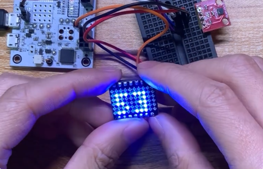 Here I connected a temperature and humidity sensor, and the screen will display the temperature and humidity values in different colors.
The picture above shows the current humidity of 53%.
Here I connected a temperature and humidity sensor, and the screen will display the temperature and humidity values in different colors.
The picture above shows the current humidity of 53%.
Summary
Driving the WS2812 with analog timing via SPI is an excellent option when hardware resources are limited and no RMT peripheral is available. Implementing this function on DWM3001CDK not only meets the requirements of the FastBond project, but also lays the foundation for the subsequent development of more complex UWB positioning visualization interfaces.