Preface
In previous articles, we all used the WiFi that comes with ESP32 for network connection. But if you want to connect your device to the Internet outdoors or in a corner without WiFi coverage, you have to get a “4G module”.
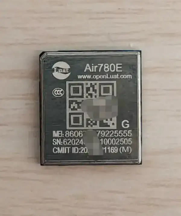
Usually the most primitive method for driving 4G modules (such as SIM800, Air724, EC20, etc.) is to use UART to send AT commands.
For example, AT+HTTPINIT, AT+HTTPPARA… This method is not only cumbersome, but also a nightmare to parse the return string. The code written is all state machine. Once the module spits out some garbled code, the program will die immediately. Manually parsing AT commands is simply a bad civilization!
In order to use the 4G module elegantly, I decided to use PPPoS(Point-to-Point Protocol over Serial). To put it simply, it is to “disguise” the serial port as a network card. In this way, the underlying TCP/IP protocol stack (LwIP) can directly take over the network. When we write the upper-layer code, we don’t have to worry about whether we are using WiFi or 4G. We can just adjust the standard Socket interface and that’s it.

Preparation
1. Hardware connection
Check that the exact modem model and firmware support UART PPP dialing; its Cat.1/Cat.4 classification alone does not guarantee this. I use Hezhou’s Air780EG. This module is a 4G+GNSS two-in-one module, which is very convenient for making equipment that requires positioning. Connect crossed TX/RX lines and a common ground. Check UART voltage levels first; use level conversion where required.
| ESP32-C3 | Modem | Purpose |
|---|---|---|
| GPIO21 (example TX) | UART RX | Data to modem |
| GPIO20 (example RX) | UART TX | Data from modem |
| GND | GND | Common ground |
| GPIO7 (original project) | RESET control circuit | Check levels, drive requirements and pulse timing |
| GPIO8 (original RX) | GPS TX | Optional independent GNSS output |
Power the modem according to its hardware documentation, not from a GPIO. The 3.9V supply mentioned below describes my setup, not a universal requirement.
PS: After the module enters the PPPOS state, the GPS cannot be output through the main serial port. The good news is that we can use another serial port of ESP32C3 to connect with the GPS serial port, so that we can use GPS and 4G PPPOS dialing at the same time. For example, I use GPIO8 to connect to GPSTX, and TXD0 and RXD0 are connected to the main serial port of the 4G module.
Core code implementation
The sample project can be created with the following command
idf.py create-project-from-example "espressif/esp_modem=1.0.3:pppos_client"Start by building the original pppos_client example, then adapt its modem configuration. The excerpts below omit headers, Kconfig and the custom DCE implementation; use the component example as the complete project entry point.
PPPoS does not eliminate AT commands. Network registration, APN setup and dialing still typically use AT commands through esp_modem. In data mode, lwIP handles upper-layer HTTP, MQTT and Socket traffic.
The whole process is actually divided into three steps: define events, initialize DCE/DTE, and switch to data mode.
1. Event Handler
PPPoS operates on an event-driven basis. We need to monitor events at the IP level. When we get the IP address, we can truly connect to the Internet successfully.
static EventGroupHandle_t event_group = NULL;
static const int CONNECT_BIT = BIT0;
static const int DISCONNECT_BIT = BIT1;

// 监听 IP 获取事件
static void on_ip_event(void *arg, esp_event_base_t event_base,
                            int32_t event_id, void *event_data)
{
    if (event_id == IP_EVENT_PPP_GOT_IP) {
        ip_event_got_ip_t *event = (ip_event_got_ip_t *)event_data;

        // 打印一下获取到的IP信息,看着就舒服
        ESP_LOGI(TAG, "Modem Connect to PPP Server");
        ESP_LOGI(TAG, "IP          : " IPSTR, IP2STR(&event->ip_info.ip));
        ESP_LOGI(TAG, "Netmask     : " IPSTR, IP2STR(&event->ip_info.netmask));
        ESP_LOGI(TAG, "Gateway     : " IPSTR, IP2STR(&event->ip_info.gw));

        // 通知主任务:我们连上网了!
        xEventGroupSetBits(event_group, CONNECT_BIT);
    } else if (event_id == IP_EVENT_PPP_LOST_IP) {
        ESP_LOGW(TAG, "Modem Disconnect from PPP Server");
        xEventGroupSetBits(event_group, DISCONNECT_BIT);
    }

}
2. Initialization and dialing
This step is the highlight. We need to initialize Netif (network interface), configure DTE (data terminal equipment, i.e. UART on the ESP32C3 side), and then initialize DCE (data communication equipment, i.e. 4G module).
void app_main(void)
{
// 1. 初始化网络接口和事件循环
ESP_ERROR_CHECK(esp_netif_init());
ESP_ERROR_CHECK(esp_event_loop_create_default());
    event_group = xEventGroupCreate();
    if (event_group == NULL) {
        ESP_LOGE(TAG, "Failed to create event group");
        return;
    }
    ESP_ERROR_CHECK(esp_event_handler_register(IP_EVENT, ESP_EVENT_ANY_ID, &on_ip_event, NULL));

    // 1.5 重启模块, 我的模块Reset脚接的GPIO7
    // Original project's active-low RESET circuit only; check your hardware.
    gpio_config_t io_config = {.pin_bit_mask = BIT64(7),
                              .mode = GPIO_MODE_OUTPUT};
    ESP_ERROR_CHECK(gpio_config(&io_config));
    ESP_ERROR_CHECK(gpio_set_level(7, 0));
    vTaskDelay(pdMS_TO_TICKS(500));
    ESP_ERROR_CHECK(gpio_set_level(7, 1));
    // Wait for modem startup according to its manual before sending AT commands.
    // 2. 配置 PPP 网络接口
    esp_modem_dce_config_t dce_config = ESP_MODEM_DCE_DEFAULT_CONFIG("cmnet"); // APN通常是cmnet
    esp_netif_config_t netif_ppp_config = ESP_NETIF_DEFAULT_PPP();
    esp_netif_t *esp_netif = esp_netif_new(&netif_ppp_config);
    if (esp_netif == NULL) {
        ESP_LOGE(TAG, "Failed to create PPP netif");
        return;
    }

    // 3. 配置串口 (DTE)
    esp_modem_dte_config_t dte_config = ESP_MODEM_DTE_DEFAULT_CONFIG();
    dte_config.uart_config.tx_io_num = 21; // TX引脚
    dte_config.uart_config.rx_io_num = 20; // RX引脚
    dte_config.uart_config.flow_control = ESP_MODEM_FLOW_CONTROL_NONE; // 没接流控线就选NONE

    // 4. 创建 Modem 对象 (这里根据实际型号选择, 由于没有Air780eg的配置,所以使用的ESP_MODEM_DCE_CUSTOM)
    ESP_LOGI(TAG, "Initializing esp_modem...");
    // CUSTOM requires a custom DCE implementation for this component version.
    // Selecting the enum alone does not add Air780EG support.
    esp_modem_dce_t *dce = esp_modem_new_dev(ESP_MODEM_DCE_CUSTOM, &dte_config, &dce_config, esp_netif);
    if (dce == NULL) {
        ESP_LOGE(TAG, "Failed to create modem; check the DCE implementation");
        return;
    }

    // 5. 检查信号质量, 如果没有信号, 很大概率会有问题, 4G模块可能没有正常工作
    int rssi, ber;
    if (esp_modem_get_signal_quality(dce, &rssi, &ber) == ESP_OK) {
        ESP_LOGI(TAG, "Signal quality: rssi=%d, ber=%d", rssi, ber);
    }

    // 6. 关键步骤:切换到 DATA 模式!
    // 这一步之后,串口就变成了透明传输的网卡通道,不能再发AT指令了
    ESP_LOGI(TAG, "Switching to Data Mode...");
    esp_err_t err = esp_modem_set_mode(dce, ESP_MODEM_MODE_DATA);
    if (err != ESP_OK) {
        ESP_LOGE(TAG, "Failed to enter data mode!");
        return;
    }

    // 7. 等待获取 IP
    ESP_LOGI(TAG, "Waiting for IP address...");
    EventBits_t bits = xEventGroupWaitBits(event_group, CONNECT_BIT, pdFALSE,
                                          pdFALSE, pdMS_TO_TICKS(60000));
    if ((bits & CONNECT_BIT) == 0) {
        ESP_LOGE(TAG, "PPP timeout; check power, registration, APN and UART");
        return;
    }

    // An assigned IP does not guarantee Internet connectivity; test DNS too.
    // If the example registers a ping command, run it from its console.
    ESP_LOGI(TAG, "PPP got IP; ready to test DNS and connectivity");

}
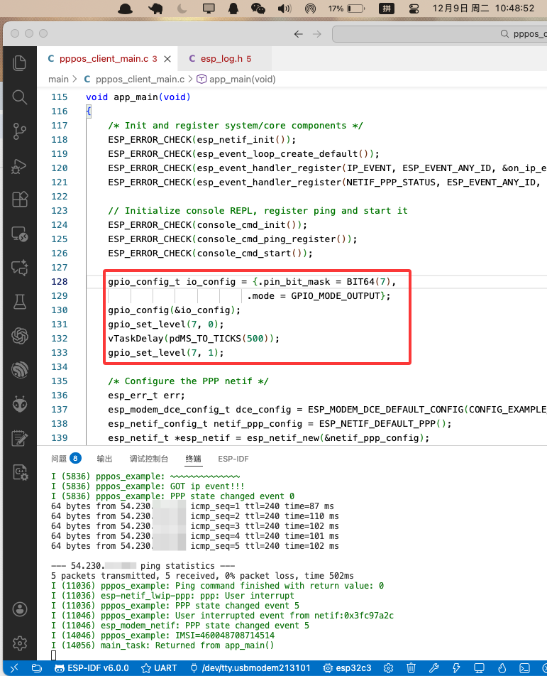
I added a modem reset before initialization in my project. Whether it is necessary, how RESET should be driven and how long startup takes depend on your hardware and firmware; the 500ms pulse is not a universal requirement.
If everything goes well, you will see the output of successful ping as shown below.
Notes on pitfalls
I encountered several pitfalls during the debugging process. Let me record them by the way:
- Power supply problem: The instantaneous current of the 4G module is very large, and ordinary 3.3V LDO usually cannot handle it, causing the module to restart repeatedly. It is recommended to power the module separately. I used a DCDC to provide 3.9V voltage to the module.
- Flow control: If your line is not connected to RTS/CTS, be sure to set
flow_controltoESP_MODEM_FLOW_CONTROL_NONEin the configuration, otherwise the data cannot be sent. - APN: Although many cards now can automatically identify the APN, it is best to specify it explicitly (usually
cmnetfor China Mobile,3gnetfor China Unicom). - Modem initialization: My setup controls RESET through GPIO. Confirm startup and AT responsiveness before registration and dialing.
Troubleshooting by symptom
| Symptom | Check first |
|---|---|
| No AT response | Power, startup delay, crossed TX/RX, baud rate and voltage levels |
| Repeated resets | Supply droop during transmission, wiring and decoupling |
| AT works but dialing fails | SIM, registration, data plan, APN and firmware PPP support |
| Registered but no PPP IP event | Custom DCE, dialing logs, UART flow control and PPP configuration |
| IP assigned but hostname requests fail | Separate DNS failures from address reachability |
| Disconnects during transfers | Supply, UART buffers, baud rate and flow control |
The original ESP-IDF version and standalone project were not recorded. These corrections improve the displayed excerpts; they are not a claim of a fresh firmware build or hardware test.
Summary
After using PPPoS, the experience of using the 4G module is almost the same as that of WiFi.
With the AsyncHTTP or MQTT library I introduced in “ESP32 Asynchronous Network Request”, you can easily deploy the device into the wild.
So, Gul’dan, what’s the price?
The answer is Power consumptionexplosion. Since the 4G module is always in data mode, if you need to send some AT commands to optimize power consumption, such as flight mode and sleep, it will be extremely troublesome. You need to switch back to Command mode every time to send commands. If you are like me and have a 4G module with built-in GPS function, the power consumption will be even more explosive. If you want to independently control the GPS power, you must use AT commands. The risk of failure to switch back and forth is very high.