Preface
In the previous article “From Scratch: Using CH592F to Make CS2 Health Badges”, I showed how to use the CH592F Bluetooth chip to create a health indicator linked to the game.
This article will introduce a technical detail of the health counter: how to use CH592F to drive WS2812.
Although the timing requirements of WS2812 are relatively strict, it can usually be achieved using GPIO flipping and precise delay, but this will occupy a lot of CPU resources and cause the Bluetooth protocol stack or other interrupt tasks to be blocked.
In order to achieve cool lighting effects with “zero” CPU usage, I decided to use the SPI peripheral of CH592F with DMA to simulate the timing of WS2812.
Principle analysis
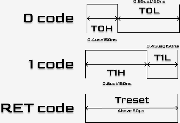
Everyone is familiar with the communication protocol of WS2812. The core is to distinguish the 0 code and 1 code through the duty cycle of high and low levels.
- 0 code: high level time is short (~0.4us), low level time is long.
- 1 code: long high level time (~0.8us), short low level time.
- The entire cycle is about 1.25us, that is, the frequency is about 800kHz.
If we set the SPI clock frequency to 4 times the WS2812 frequency (about 3.2MHz), then the time it takes to send one byte (8 bits) of SPI data exactly corresponds to 2 WS2812 bit cycles (because here we use 4 SPI bits to represent 1 WS2812 bit).
- Simulate 0 code: Send binary
1000(0x8), that is, 1 high level + 3 low levels. - Simulate 1 code: Send binary
1110(0xE), that is, 3 high levels + 1 low level.
In this way, we only need to open a cache in the memory, “expand” the RGB color data into the corresponding SPI data, and then send it through DMA with one click, which can completely liberate the CPU.
Core code implementation
1. Initialize SPI
First, you need to configure SPI0 as host mode. The system main frequency of CH592F is usually 48MHz. In order to make up the SPI clock of 3.2MHz, we need to set the frequency division coefficient.
48MHz / 15 = 3.2MHz.
void NeoPixelController::begin() {
// 配置GPIO,PA12/13/14通常对应SPI0
GPIOA_ResetBits (GPIO_Pin_12);
GPIOA_ModeCfg (GPIO_Pin_12 |GPIO_Pin_13 | GPIO_Pin_14, GPIO_ModeOut_PP_5mA);

    // 初始化SPI0
    SPI0_MasterDefInit();
    // 设置分频,15分频得到3.2MHz
    // 注意:实际调试中可能需要根据示波器微调
    SPI0_CLKCfg (15);

    // 发送复位信号(WS2812需要 >50us 的低电平复位)
    // 这里发送一段全0数据即可
    memset (_spiBuffer, 0, 24);
    SPI0_MasterDMATrans (_spiBuffer, 24);

}
2. Data conversion (GRB -> SPI)
This is the most critical step. We need to expand the compact RGB (actually GRB sequence) data in the memory into the waveform data required by the SPI bus. Two macros are defined here to represent the 4-bit data fragments sent by SPI:
GRB_CODE_0:0x8(corresponds to binary 1000)GRB_CODE_1:0xE(corresponds to binary 1110)
To save space, our one-byte SPI buffer stores two WS2812 bits.
// 补充宏定义,用于生成波形
##define GRB_CODE_0 0x8
##define GRB_CODE_1 0xE

void NeoPixelController::convertGRBtoSPI (const uint8*t *grb, uint8*t *spi, uint16_t len) {
// len 是LED的数量
// 每个LED 3个字节颜色,每个颜色位需要4位SPI数据
// 所以SPI buffer长度 = len _ 3 _ 4 (bytes)
memset (spi, 0, len \_ 3 \_ 4);

    for (uint16_t i = 0; i < len; i++) {
        for (uint8_t j = 0; j < 3; j++) { // R, G, B 三个通道
            for (uint8_t k = 0; k < 4; k++) { // 每个字节8位,分为4组,每组2位
                for (uint8_t m = 0; m < 2; m++) { // 处理每组中的2位
                    // 检查GRB颜色数据的特定位是否为1
                    // 逻辑比较绕,本质就是从高位到低位通过掩码取值
                    if (grb[3 * i + j] & (0x80 >> (2 * k + m))) {
                        // 如果是1,SPI buffer填入 1110 (高位) 或 1110 (低位)
                        spi[3 * 4 * i + 4 * j + k] |= (GRB_CODE_1 >> (m * 4));
                    } else {
                        // 如果是0,SPI buffer填入 1000 (高位) 或 1000 (低位)
                        spi[3 * 4 * i + 4 * j + k] |= (GRB_CODE_0 >> (m * 4));
                    }
                }
            }
        }
    }

}
3. DMA send
After the data conversion is completed, the sending process is very simple. Directly call the DMA transfer function of CH592F, and the CPU can handle the Bluetooth connection or sleep.
void NeoPixelController::show() {
// 1. 将颜色数据转换为SPI波形数据
convertGRBtoSPI (\_grbBuffer, \_spiBuffer, \_numLeds);
// 2. 启动DMA传输
// 长度计算:LED数量 _ 3(RGB) _ 4(膨胀系数)
SPI0*MasterDMATrans (\_spiBuffer, \_numLeds * 3 \_ 4);
}
Encapsulation and calling
For ease of use, I encapsulated it into a NeoPixelController class, which imitated the interface style of Arduino Adafruit _NeoPixel.
Header file NeoPixel.h:
##ifndef NEOPIXEL_H
##define NEOPIXEL_H

##include "CH59x_common.h"

class NeoPixelController {
public:
// 构造函数,需要指定LED数量和SPI buffer大小
// 注意:\_spiBuffer 最好在外部申请或者在类中动态申请
NeoPixelController (uint16_t numLeds, uint8_t spiInstance = 0);

    void begin();
    void show();
    void setPixelColor(uint16_t index, uint32_t color);
    void setPixelHSV(uint16_t index, uint8_t hue, uint8_t sat, uint8_t val);
    void clear();
    void setBrightness(uint8_t brightness);

    // 简单的颜色工具
    static uint32_t Color(uint8_t r, uint8_t g, uint8_t b);

private:
uint16_t \_numLeds;
uint8_t \_spiInstance;
uint8_t \_brightness;

    // 这里为了演示方便,假设最大支持一定数量,实际应动态分配
    uint8_t _grbBuffer[100 * 3];
    uint8_t _spiBuffer[100 * 3 * 4];

    void convertGRBtoSPI(const uint8_t *grb, uint8_t *spi, uint16_t len);
    uint32_t colorHSV(uint8_t hue, uint8_t sat, uint8_t val);

};

##endif
Called in the main program Main.c:
NeoPixelController strip(32); // 控制32颗灯珠

int main() {
    SetSysClock(CLK_SOURCE_PLL_48MHz);
    strip.begin();
    strip.setBrightness(50);

    while(1) {
        // 跑个彩虹特效
        static uint8_t hue = 0;
        strip.rainbow(hue++, 255, 255);
        strip.show();
        DelayMs(10);
    }
}
Summary
The biggest advantage of driving WS2812 through SPI+DMA is that the timing is extremely stable and does not consume CPU computing power. This is very important for a single-core Bluetooth SoC such as CH592F, which avoids the problem of unstable Bluetooth connections caused by turning off interrupt write timing.
The only price is that the memory usage is slightly larger (each LED requires 12 bytes of SPI buffer), but for decorative applications with dozens of LEDs, the RAM of CH592F is more than enough.
Additional information
The code can not only run on CH592 series chips, but also on CH582 series chips.