Preface
In the previous article, you were already familiar with how to burn the program to ESP32, and successfully lit up an LED light, if you have strong hands-on skills. So the previous section taught you how to make a lamp that supports HomeKit.
This article will replace the LED in the previous article with a servo. As for why I used servo, it was because I didn’t want to destroy the original structure of the switch and wanted to use a non-invasive method to expand the existing light switch.
The second half will continue to integrate HomeKit’s switch callback and servo control code, so that Siri’s “turn on/off lights” command can actually push the physical switch.
Re-enable environment variables
If you restarted your computer or shut down the subsystem after reading the previous article, you will need to reconfigure the ESP-IDF environment variables, and you may also need to remount the device to the subsystem. Use command
. $HOME/esp/esp-idf/export.shThat’s it
control servo
0x01 control signal
To control the servo, you have to send the correct instructions. The servo I use looks like this:
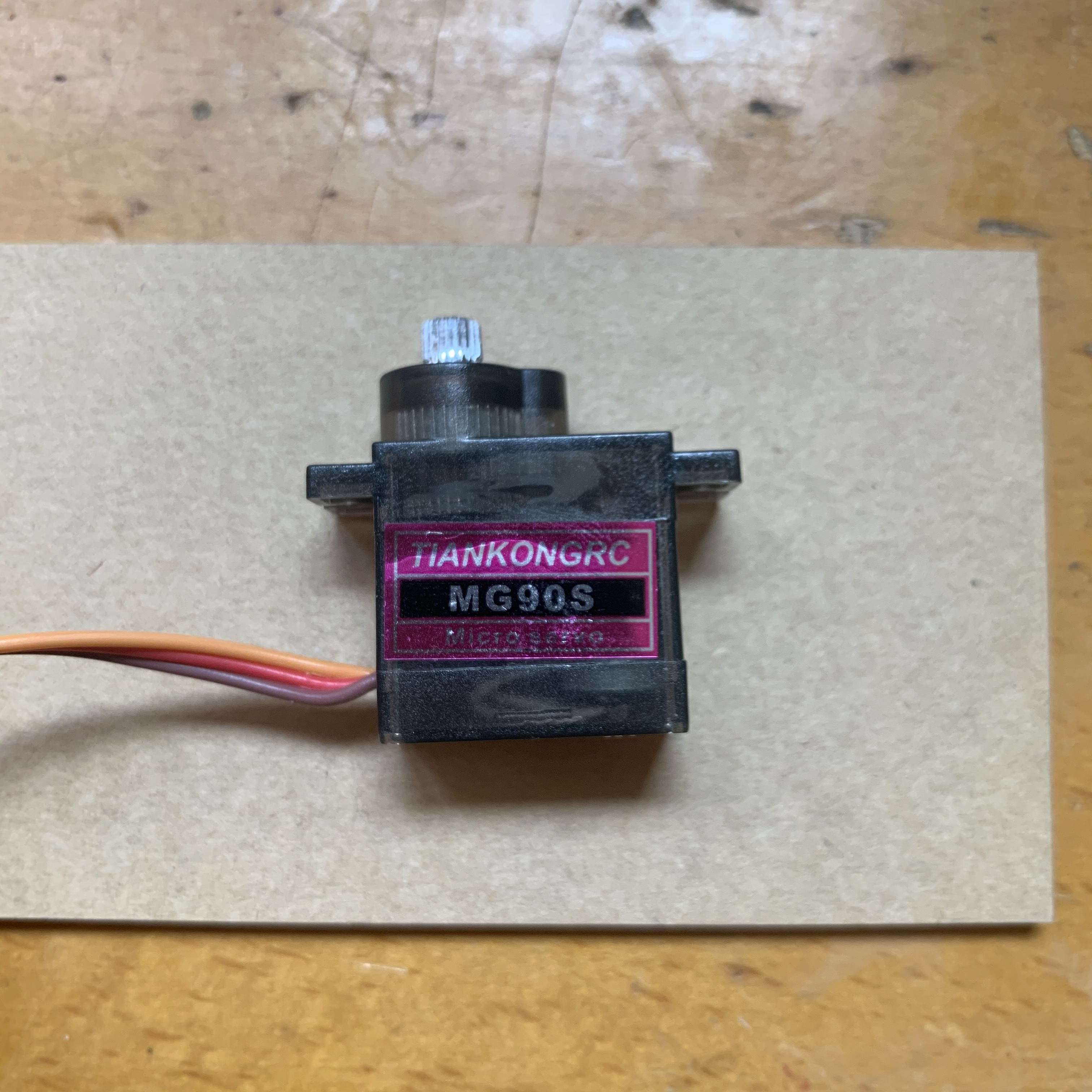 The signal frequency is 50Hz. The so-called command is the duration (width/length) of the high-level pulse in each cycle.
The red color in the video is the actual signal. It can be seen that as the duration of the high level becomes longer, the angle of the servo becomes larger and larger.
The signal frequency is 50Hz. The so-called command is the duration (width/length) of the high-level pulse in each cycle.
The red color in the video is the actual signal. It can be seen that as the duration of the high level becomes longer, the angle of the servo becomes larger and larger.
| Duration | Corresponding angle |
|---|---|
| 0.50ms | 0° |
| 1.50ms | 90° |
| 2.50ms | 180° |
0x02 control related codes
For this kind of servo controlled by pulse signal, PWM can be used for control. You can easily find relevant examples by consulting the official guide, and there are even ready-made demos that you can use directly (I have to say that the official examples are really detailed). Okay, now you don’t have to write it yourself (fortunately, you don’t have to, otherwise you would have to use a for loop + delay to manually generate pulse signals to control) Go directly to mcpwm_servo_control_example.c. Just copy or download it. For convenience, you can copy it to led.c in the previous article, but remember to comment out all the previous content first, because you will need to use those codes in the future. Among them
##define SERVO_MIN_PULSEWIDTH 1000 //Minimum pulse width in microsecond
##define SERVO_MAX_PULSEWIDTH 2000 //Maximum pulse width in microsecond
##define SERVO_MAX_DEGREE 90 //Maximum angle in degree upto which servo can rotate
It needs to be modified. According to my servo parameters, modify it to
##define SERVO_MIN_PULSEWIDTH 500 //Minimum pulse width in microsecond
##define SERVO_MAX_PULSEWIDTH 2500 //Maximum pulse width in microsecond
##define SERVO_MAX_DEGREE 180 //Maximum angle in degree upto which servo can rotate
And because my board does not lead to pin 18, I will change it to pin 2 in the previous article.
static void mcpwm_example_gpio_initialize(void)
{
    printf("initializing mcpwm servo control gpio......\n");
    mcpwm_gpio_init(MCPWM_UNIT_0, MCPWM0A, 18);    //Set GPIO 18 as PWM0A, to which servo is connected
}
Change to
static void mcpwm_example_gpio_initialize(void)
{
    printf("initializing mcpwm servo control gpio......\n");
    mcpwm_gpio_init(MCPWM_UNIT_0, MCPWM0A, 2);    //Set GPIO 2 as PWM0A, to which servo is connected
}
至此,代码就修改完成了。
0x03 Burn it in
There’s nothing much to say about the flashing process, it’s just pretty much the same as before.
After compiling the project
make -C examples/esp32/led allFirst perform earse_flash
make -C examples/esp32/led erase_flashThen flash.
make -C examples/esp32/led flash0x04 Let’s see the effect
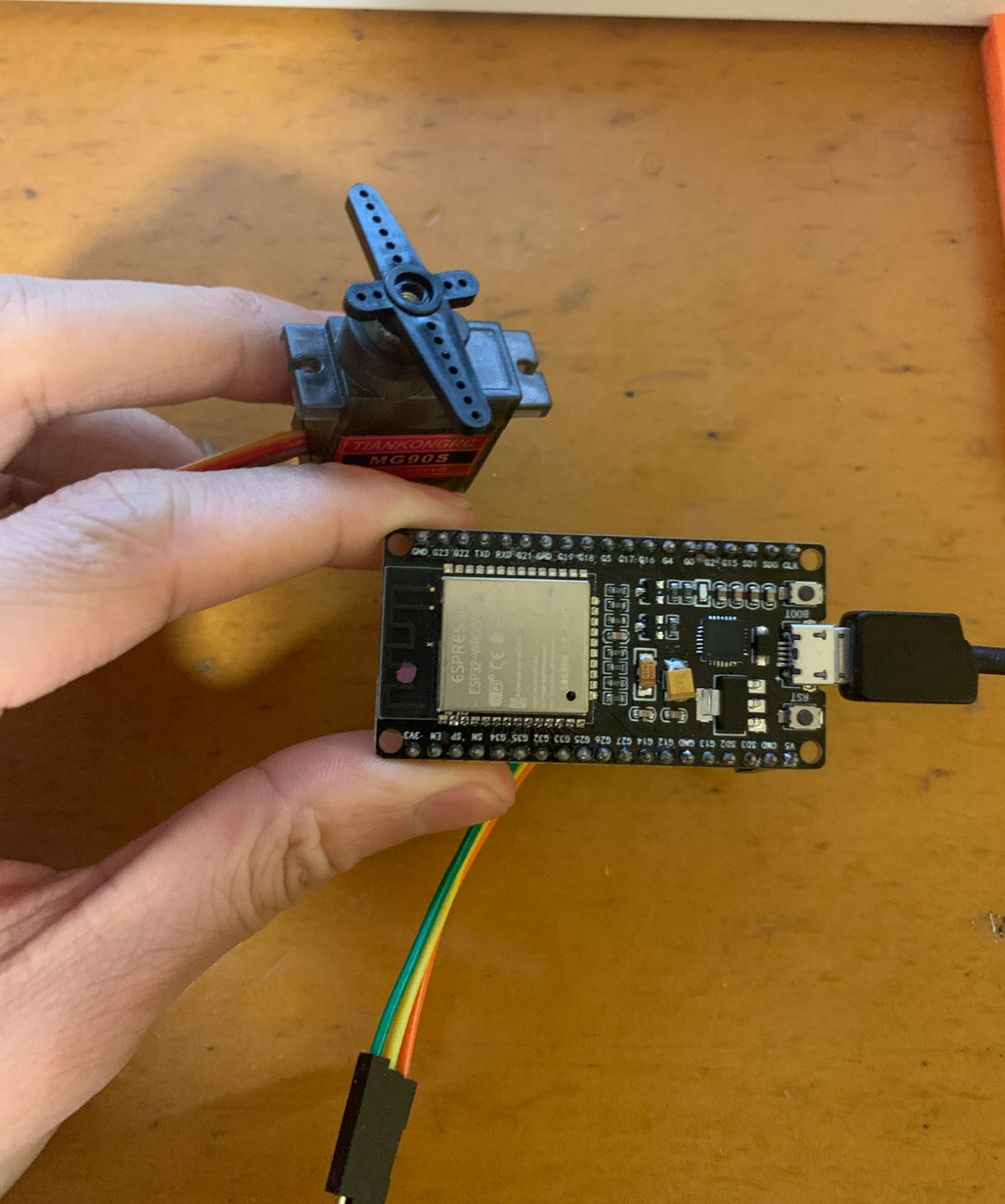 Since the code burned in is only for controlling the servo, it cannot be added to HomeKit.
When the flashing is completed, the servo will slowly turn from 0 degrees to 180 degrees, then quickly return to 0 degrees, then turn from 0 degrees to 180 degrees again, and then loop endlessly.
Since the code burned in is only for controlling the servo, it cannot be added to HomeKit.
When the flashing is completed, the servo will slowly turn from 0 degrees to 180 degrees, then quickly return to 0 degrees, then turn from 0 degrees to 180 degrees again, and then loop endlessly.
Note:
The code to control the specific degree of rotation is as follows. It is recommended that you are familiar with it. It will be used in the next article.
// 先计算出目标角度对应的高电平持续时间
angle = servo_per_degree_init(count);
// 设置PWM信号
mcpwm_set_duty_in_us(MCPWM_UNIT_0, MCPWM_TIMER_0, MCPWM_OPR_A, angle);
Integrate HomeKit and servo control
My turn, draw a card. Activate the magic card - fusion!
Two things have been covered before: the first article introduced how to control the LED on and off, and the first half of this article introduced how to rotate the servo to a specified angle. The next thing to do is to connect the switch status callback in HomeKit Demo to the MCPWM servo control.
Detection before fusion
In the LED Demo, the led_write(bool status) function is called every time the light is turned on or off, so we only need to rotate the servo to the corresponding angle based on the status value passed in.
First extract the required methods from mcpwm_servo_control_example.c, the contents are as follows:
// 引入的头文件

##include "driver/mcpwm.h"
##include "soc/mcpwm_periph.h"
##include "esp_attr.h"

// 舵机参数的宏定义
##define SERVO_MIN_PULSEWIDTH 500 // 最小脉冲时间ms
##define SERVO_MAX_PULSEWIDTH 2500 // 最大脉冲时间ms
##define SERVO_MAX_DEGREE 180 // 舵机最大可旋转角度

// 初始化2号端口为PWM
static void mcpwm_example_gpio_initialize(void)
{
    printf("initializing mcpwm servo control gpio......\n");
    mcpwm_gpio_init(MCPWM_UNIT_0, MCPWM0A, 18);    //Set GPIO 2 as PWM0A, to which servo is connected
}

// 该方法输入目标角度,输出对应高电平脉冲宽度单位us
static uint32_t servo_per_degree_init(uint32_t degree_of_rotation)
{
    uint32_t cal_pulsewidth = 0;
    cal_pulsewidth = (SERVO_MIN_PULSEWIDTH + (((SERVO_MAX_PULSEWIDTH - SERVO_MIN_PULSEWIDTH) * (degree_of_rotation)) / (SERVO_MAX_DEGREE)));
    return cal_pulsewidth;
}

// 开灯函数
void turn_on(void *arg)
{
    uint32_t angle;
    //1. mcpwm gpio 初始化
    mcpwm_example_gpio_initialize();
    //2. 初始化 mcpwm 配置
    printf("Configuring Initial Parameters of mcpwm......\n");
    mcpwm_config_t pwm_config;
    pwm_config.frequency = 50; // 舵机信号频率为50Hz,每个周期时长20ms
    pwm_config.cmpr_a = 0;     //duty cycle of PWMxA = 0
    pwm_config.cmpr_b = 0;     //duty cycle of PWMxb = 0
    pwm_config.counter_mode = MCPWM_UP_COUNTER;
    pwm_config.duty_mode = MCPWM_DUTY_MODE_0;
    mcpwm_init(MCPWM_UNIT_0, MCPWM_TIMER_0, &pwm_config); //应用上面配置到 PWM0A & PWM0B
    // 旋转角度
    printf("Angle of rotation: %d\n", 0);
    // 计算60度对应的脉冲宽度
    angle = servo_per_degree_init(60);
    printf("pulse width: %dus\n", angle);
    mcpwm_set_duty_in_us(MCPWM_UNIT_0, MCPWM_TIMER_0, MCPWM_OPR_A, angle);
    vTaskDelay(10); //Add delay, since it takes time for servo to rotate, generally 100ms/60degree rotation at 5V
    vTaskDelete(NULL);
}

// 关灯函数
void turn_off(void *arg)
{
    uint32_t angle;
    //1. mcpwm gpio 初始化
    mcpwm_example_gpio_initialize();
    //2. 初始化 mcpwm 配置
    printf("Configuring Initial Parameters of mcpwm......\n");
    mcpwm_config_t pwm_config;
    pwm_config.frequency = 50; //frequency = 50Hz, i.e. for every servo motor time period should be 20ms
    pwm_config.cmpr_a = 0;     //duty cycle of PWMxA = 0
    pwm_config.cmpr_b = 0;     //duty cycle of PWMxb = 0
    pwm_config.counter_mode = MCPWM_UP_COUNTER;
    pwm_config.duty_mode = MCPWM_DUTY_MODE_0;
    mcpwm_init(MCPWM_UNIT_0, MCPWM_TIMER_0, &pwm_config); //ConfigurePWM0A & PWM0B with above settings
    printf("Angle of rotation: %d\n", 0);
    // 计算120度对应的脉冲宽度
    angle = servo_per_degree_init(120);
    printf("pulse width: %dus\n", angle);
    mcpwm_set_duty_in_us(MCPWM_UNIT_0, MCPWM_TIMER_0, MCPWM_OPR_A, angle);
    vTaskDelay(10); //Add delay, since it takes time for servo to rotate,generally 100ms/60degree rotation at 5V
    vTaskDelete(NULL);
}

// 最后修改led_write函数为
void led_write(bool on)
{
    if (on)
    {
        // 接收到开灯命令,执行开灯任务
         xTaskCreate(turn_on, "turn_on", 4096, NULL, 5, NULL);
    }
    else
    {
        // 接收到关灯命令,执行关灯任务
        xTaskCreate(turn_off, "turn_off", 4096, NULL, 5, NULL);
    }
}
The complete file is located at HomeKitServoLight.c
Let’s take a look at the effect
Now servo will listen to our instructions!
Coupled with a simple structure, the switch can be controlled.
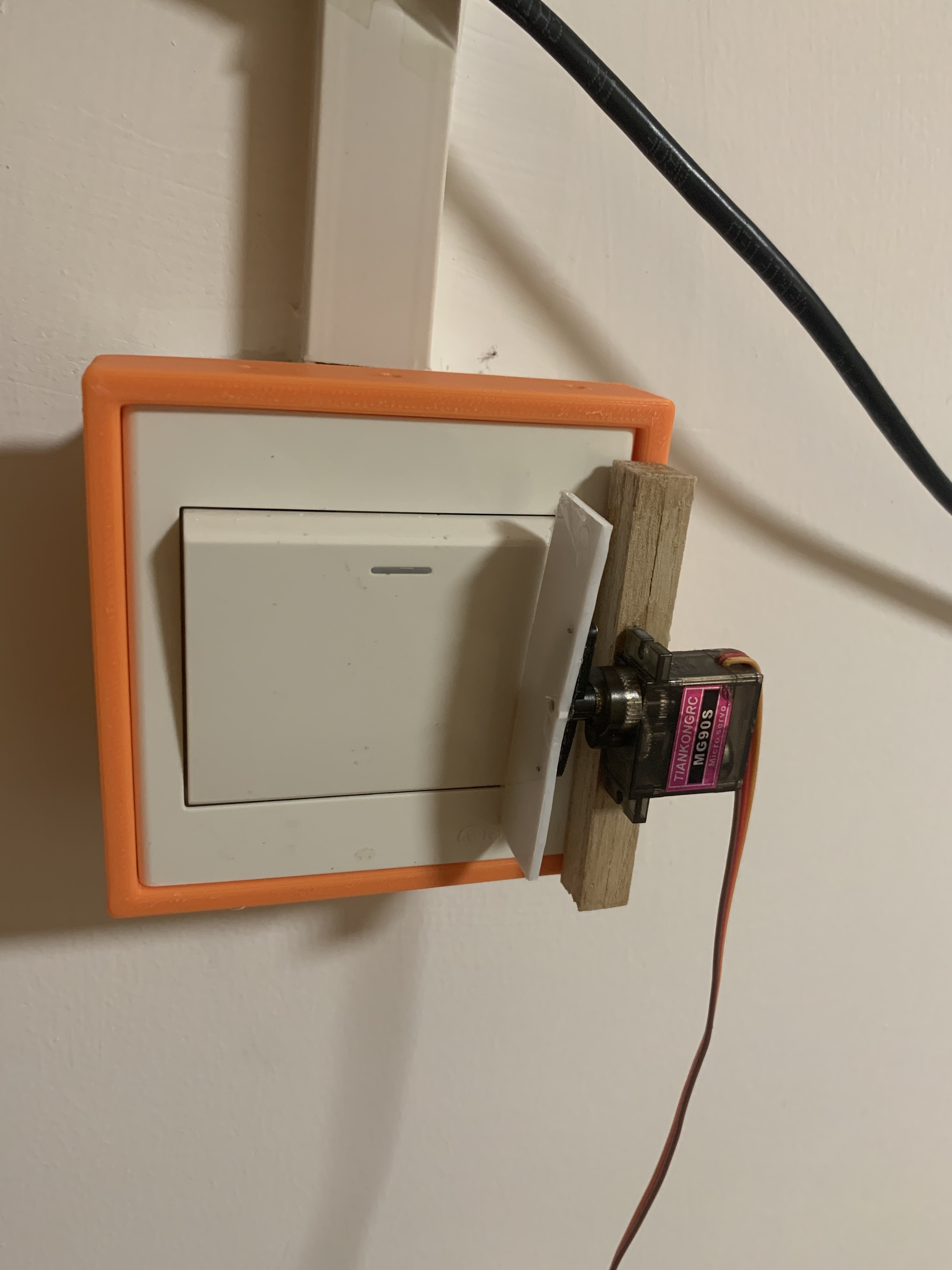
To be honest, I originally planned the “Structural Design Chapter” of the fourth part, but I didn’t expect that this project… actually ended. So, let this “humble” structure become the final product of this series. It’s ugly, but it works great!
References: