background
Since there is no bedside light switch where I live, I have to get out of bed to turn off the light every time. It happened that I bought an extra ESP32 last time, and what happened was that Big Yellow Cat recently sent me a video of controlling his ESP8266 through HomeKit. Hence this article. The goal is clear, that is, connect ESP32 to HomeKit and control my switches through Siri.
Preparation *
Environment Environment Environment. You can start working only after configuring the environment. In essence, configuring the environment is the most tedious thing.
The operating system I use is Windows 10 18363.719
But the real development environment is Ubuntu 18.04 LTS located on Windows Subsystem for Linux (this operating system can be downloaded from the Microsoft Store that comes with Windows 10) That’s right, I put on a baby.
0x01 Download esp-homekit-demo
https://github.com/maximkulkin/esp-homekit-demo.git
Open a terminal, go to your favorite folder, and use the command
git clone https://github.com/maximkulkin/esp-homekit-demo.gitDownload esp-homekit-demo
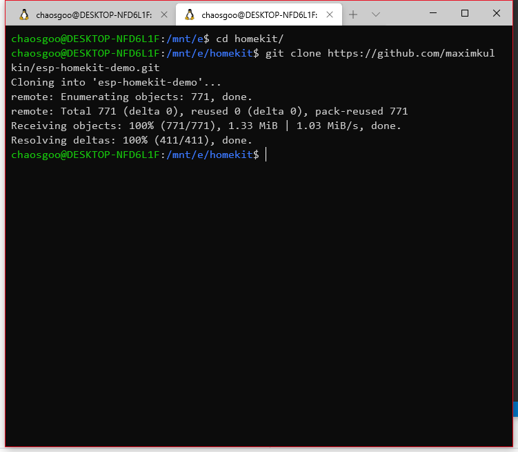
0x02 Download esp32 development environment
cd to ~ and use mkdir to create the esp folder and cd into
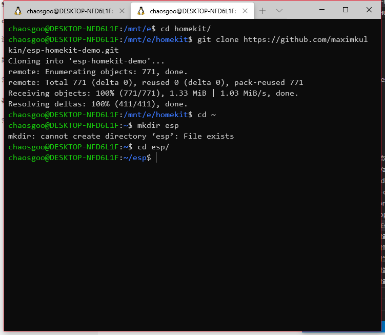 This is because I have already created this file, so the creation failed.
Download esp-idf
git clone --recursive https://github.com/espressif/esp-idf.git0x03 Setting tool
When executing commands, the entire process is automatic, and missing dependent tools will also be automatically downloaded. Perhaps the biggest obstacle comes from the network, so you can consider using a proxy.
cd ~/esp/esp-idf
./install.sh
This process is time consuming, please be patient.
0x04 Set environment variables
execute command
. $HOME/esp/esp-idf/export.shNow that everything is ready, let’s use an LED to verify the development environment and practice. Here we go.
Light up your LED
0x01 Initialize and synchronize the project
Go back to the esp-homekit-demo folder and use the command
git submodule update --init --recursive0x02 Configure wifi
In the esp-homekit-demo folder, there is a wifi.h.sample file with the content
##define WIFI_SSID "mywifi"
##define WIFI_PASSWORD "mypassword"
Replace mywifi with the SSID of the target Wi-Fi and mypassword with the password of the target Wi-Fi. Then rename the file to wifi.h
0x04 Mount the device to the subsystem
Since Ubuntu is just our subsystem, it cannot directly detect the ESP32 plugged into the computer. It needs to be mounted on the subsystem to detect it. Don’t worry, it’s easy, just copy the command.
The first thing to do is to plug your ESP32 into the host computer, and then go to the Windows Device Manager to view the port number. Here is my computer as an example.
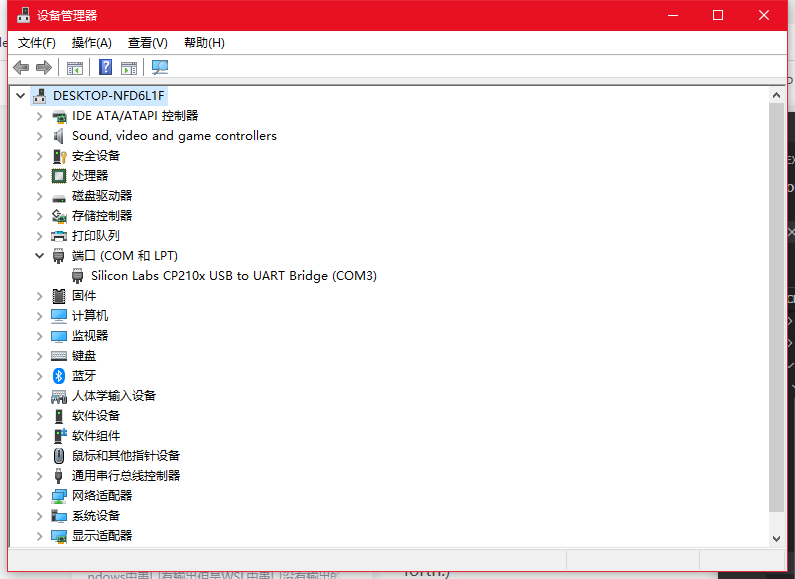 You can see that my ESP32 is on the COM3 port, so execute the command in the terminal
sudo chmod 666 /dev/ttyS3
stty -F /dev/ttyS3 -a
stty -F /dev/ttyS3 sane 115200
In this way, my ESP32 is connected to the ttyS3 interface of the subsystem
0x03 Configure development board related parameters
In the terminal, go back to the previous esp-homekit-demo folder and use the command
make -C examples/esp32/led menuconfigSelect Serial flasher config and change the port number to ttyS3
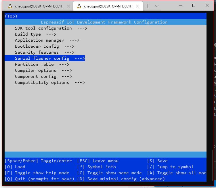
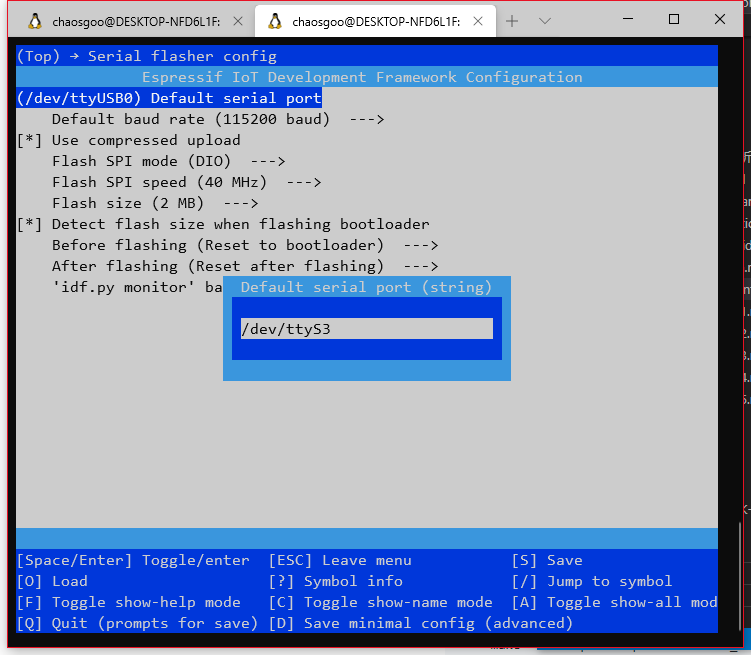 Use esc to exit and save
0x04 Compile project
Use command
make -C examples/esp32/led allThis process is also time-consuming, so please be patient.
when appears
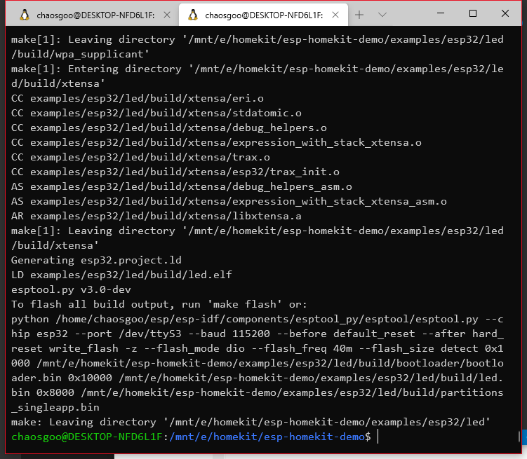 Indicates that the build was successfully completed
0x05 Flashing program
In order to prevent previously burned programs from being affected, the flash needs to be erased before each flashing.
Use command
make -C examples/esp32/led erase_flashWhen Serial port /dev/ttyS3 appears
Connecting…
Sometimes you may need to hold down the boot button on the ESP32 board for a few seconds and then let go to clear and burn normally.
Execute flashing command
make -C examples/esp32/led flashYou may also need to press the boot button for a few seconds
0x06 Connect to peripherals to view the effect
In the LED demo project, the enabled GPIO is No. 2, so we need to connect the LED to pin No. 2. Since I didn’t have a separate LED on hand, I used an LED light board for demonstration. Pin 2 is connected to the positive pole of the LED, and the negative pole of the LED is connected to GND.
Open your iPhone, then launch Home, click Add Accessory, and select I don’t have or can’t scan the code.
At this time, you can view the Sample LED in the nearby accessories and select it. Although there will be a prompt for uncertified accessories, don’t ignore it, the motor is still added. Then enter the code 11111111. Wait a moment for the addition to be successful.
Now you can say “Hey, Siri, turn on the lights” or “Hey, Siri, turn off the lights” on your phone.

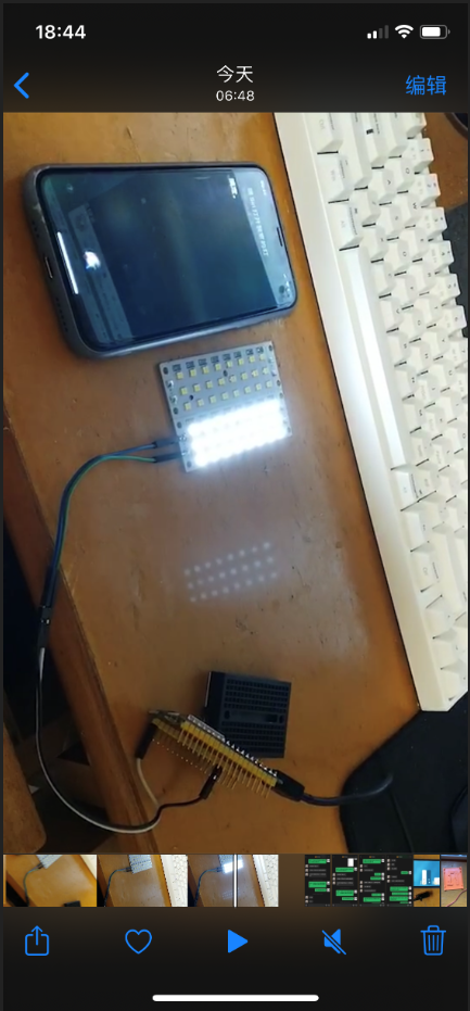
Preview for the next issue: Connect your home lights to HomeKit Part 2 (servo part)
References: Build an ESP32 development environment under the Linux subsystem of Win10