Unique gold counter (StatTrak) replica actual combat
In CS:GO, some weapons have a device called StatTrak, which can record the number of enemies killed by the player in the game. I thought this device was very interesting, so I wanted to make one.
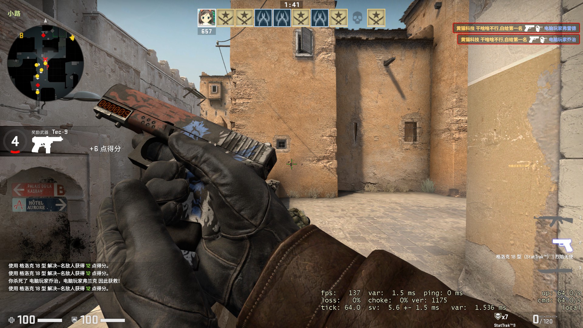
In order to observe this device up close, I spent a huge sum of 8.8 yuan to buy a Glock 18 (StatTrak™)|Fire Angel, and killed everyone in the man-machine battle.
Plan iteration process
Since it is just a counter, it is essentially a display screen that can be customized to display content. But to achieve “both form and spirit”, model selection and detailed design are very critical.
Solution 1: OLED 12832 + Arduino
After some searching on Google, I found that an old man on YouTube had done something similar. The solution he used was 12832 OLED + Arduino.
Question: OLED only has white and blue colors, so how to achieve the orange effect in the game?
Solution: Add an orange filter membrane. The price of the filter membrane used by this old man has taken off, and it is only a small piece. Isn’t it just an orange plastic piece? Can’t it be used for windows? So I spent a lot of money to buy a piece of orange translucent plastic film and stuck it on the OLED, and the effect was quite good.
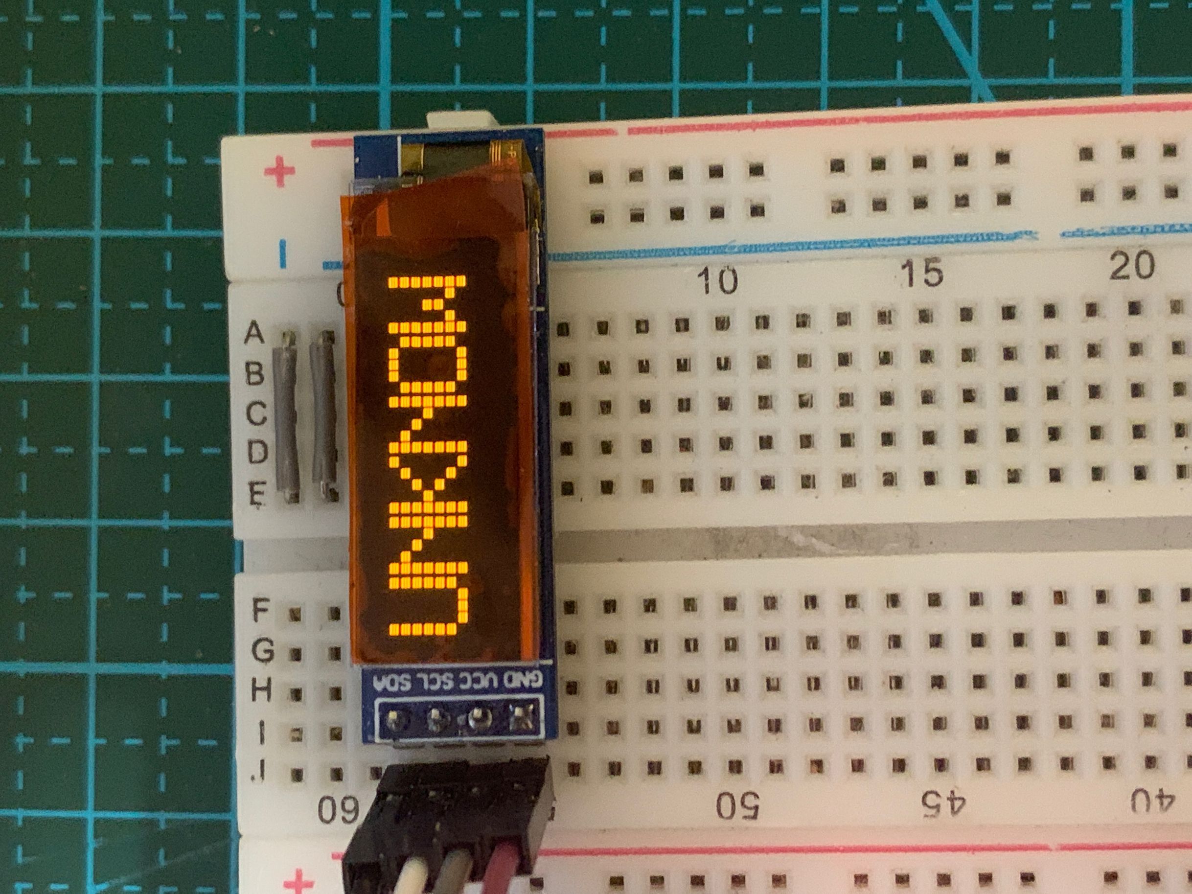
I thought this was too small to be miniaturized. (2020-11-21 Looking back now, it’s not too difficult anymore)
Solution 2: LED dot matrix screen + MAX7219
After playing around on a certain product, I found that I couldn’t find a suitable dot matrix screen. However, there was a 30mm high that met some requirements, so I decided to scale it up and make a real object.
| Technical Highlights | Details |
|---|---|
| Driver chip | MAX7219 (SPI interface cascade) |
| Dot matrix specifications | 8x8 LED module x N |
| PCB Design | KiCad Drawing |
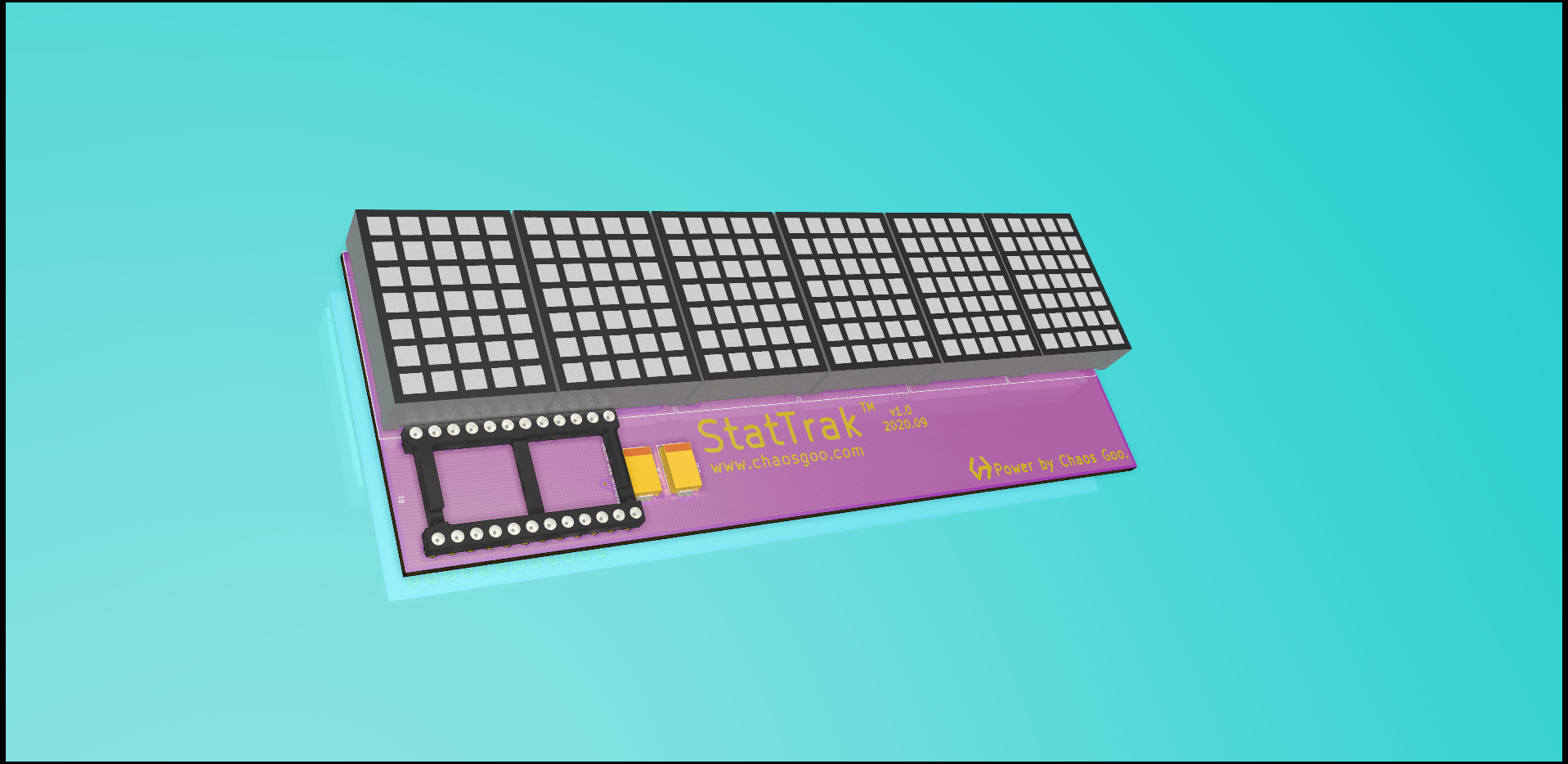
This is what it looked like after soldering. Why does it look different? My first attempt failed. The dot-matrix display seller’s documentation was wrong. I measured the connections myself, but then made another mistake while drawing the schematic.
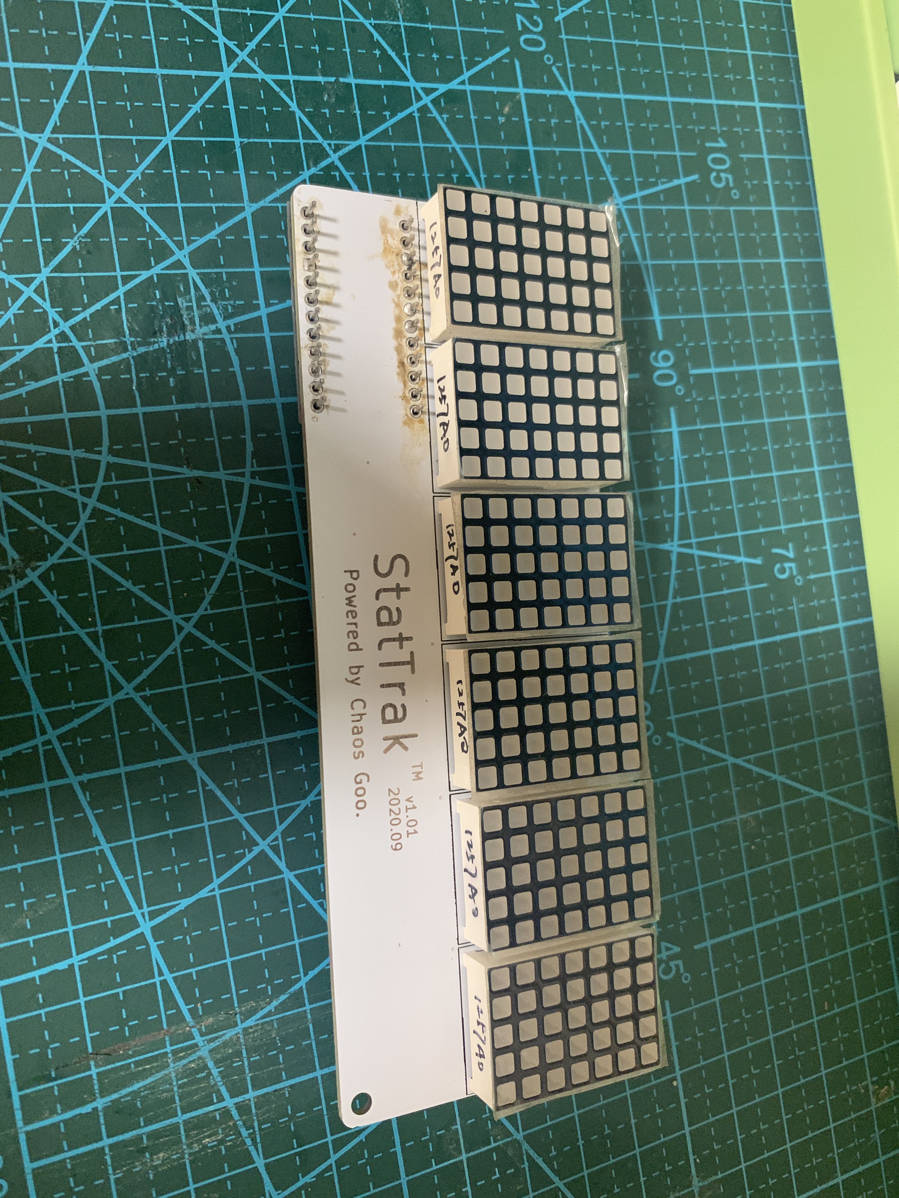
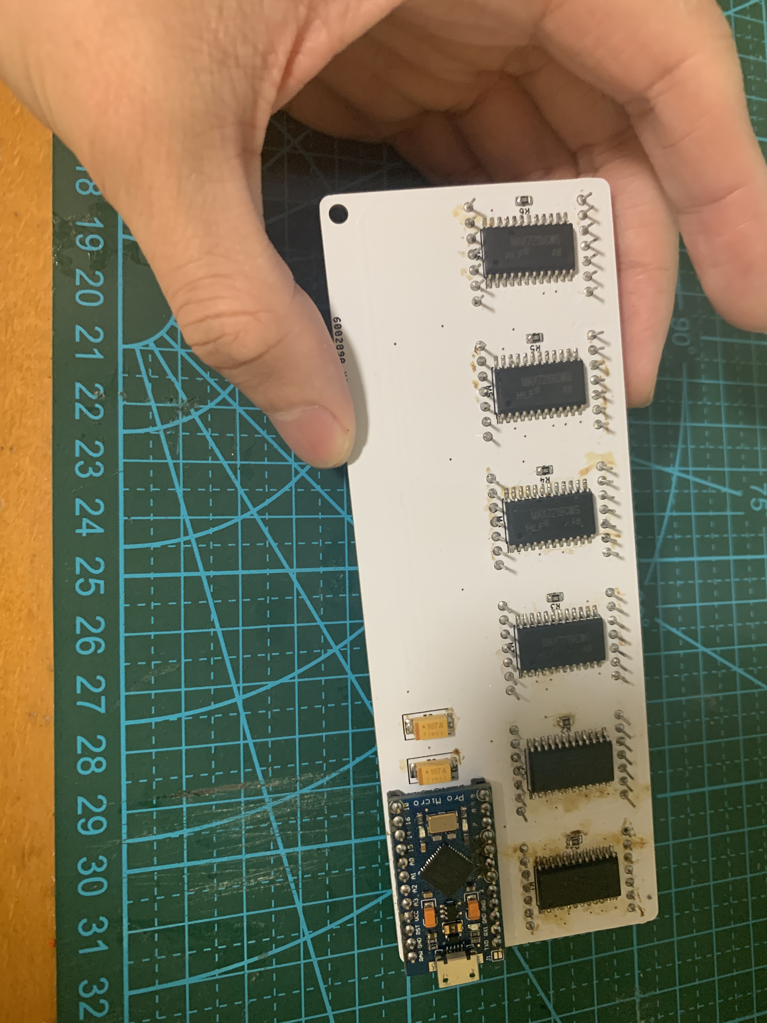
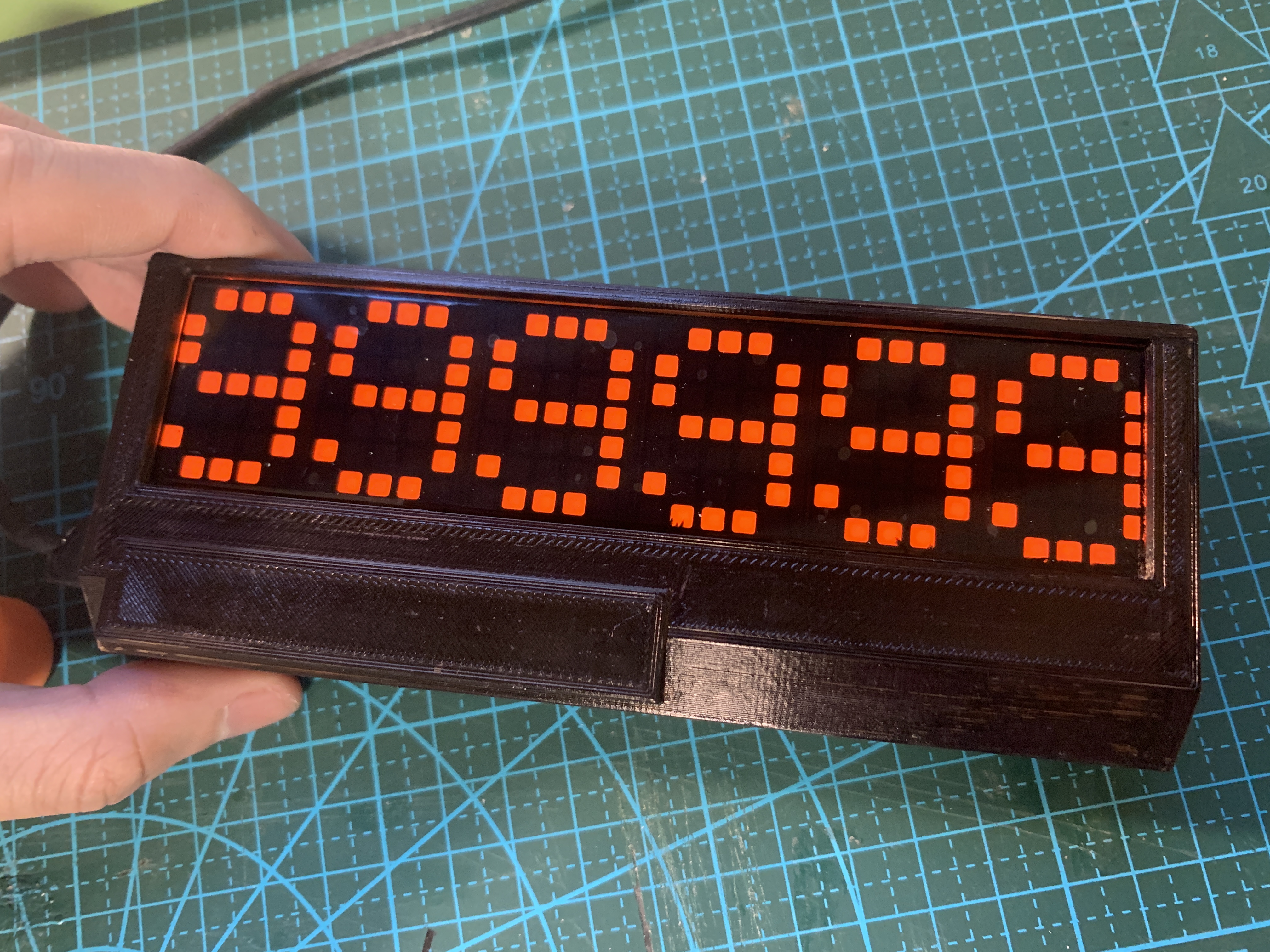
It’s really ugly. Under what circumstances did I have the idea to use a black marker to paint it black?
Option 3: HDSP2072 antique screen + homemade core board
One time when I was shopping at Xianyu, I found a screen with parameters that quite met the requirements. I asked about the price, which was 72, so I excused myself. But I gritted my teeth and bought it.
This screen is the stock from the last century. It was originally used on mobile phones.
| Hardware Specifications | Details |
|---|---|
| Screen model | HDSP-2072 |
| Main control chip | ATmega32U4 (removed from Pro Micro) |
| Interface | Type-C (16P) |
| PCB process | JLC 5 yuan 24 hours expedited SF free shipping |
Fortunately, the Arduino of this century can also be driven normally
Then I felt that this time I could draw a complete board directly without using an external Arduino. It was a good opportunity to practice my skills. I just copied (simplified) the Pro Micro schematic diagram provided by SparkFun, and I finally finished the drawing in one day.
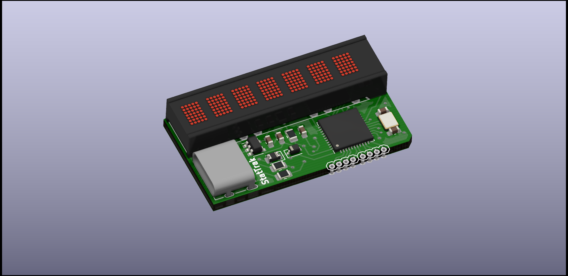
Then ask JLC for 24-hour expediting. After 24 hours, the board arrived home.
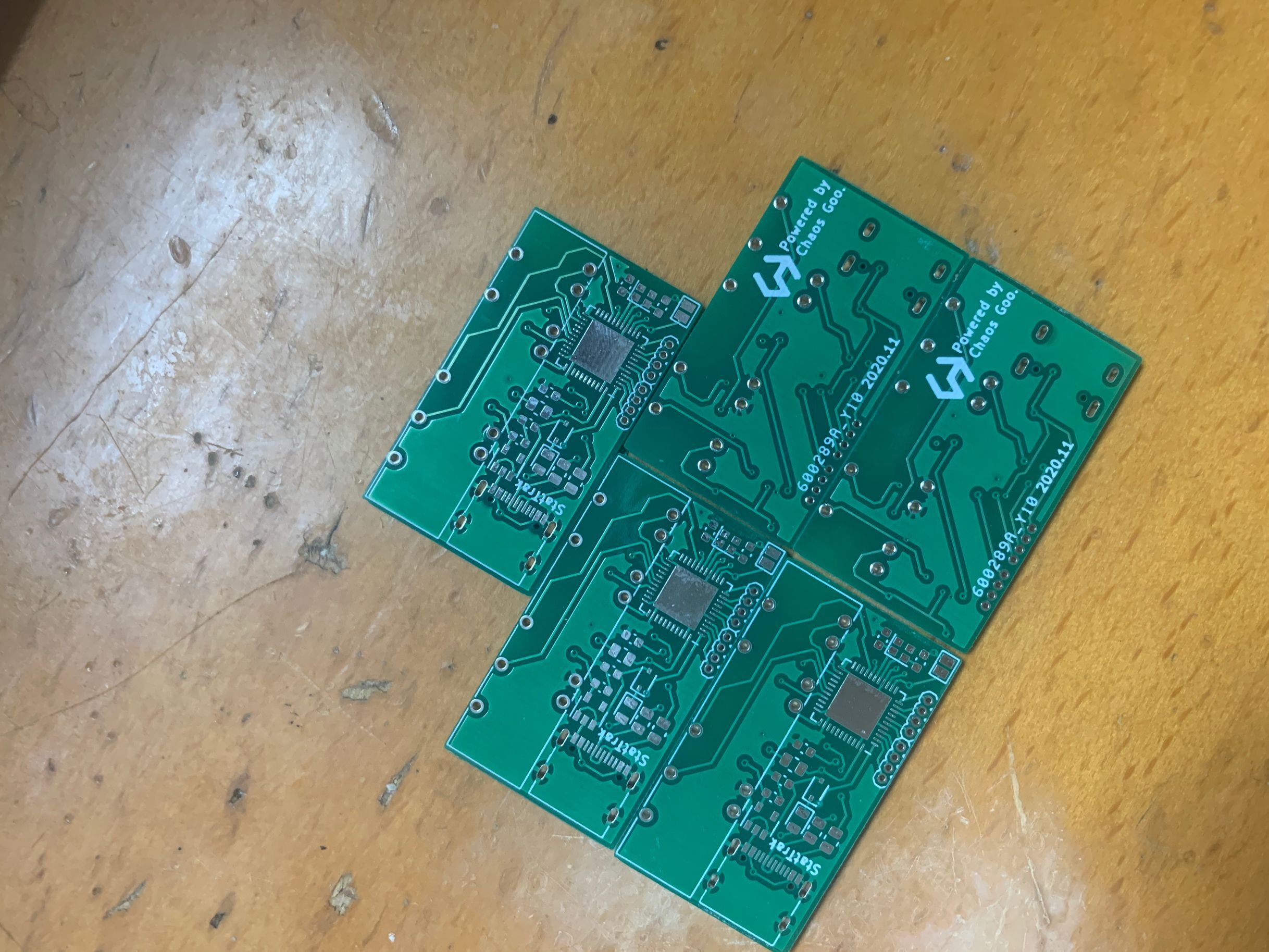
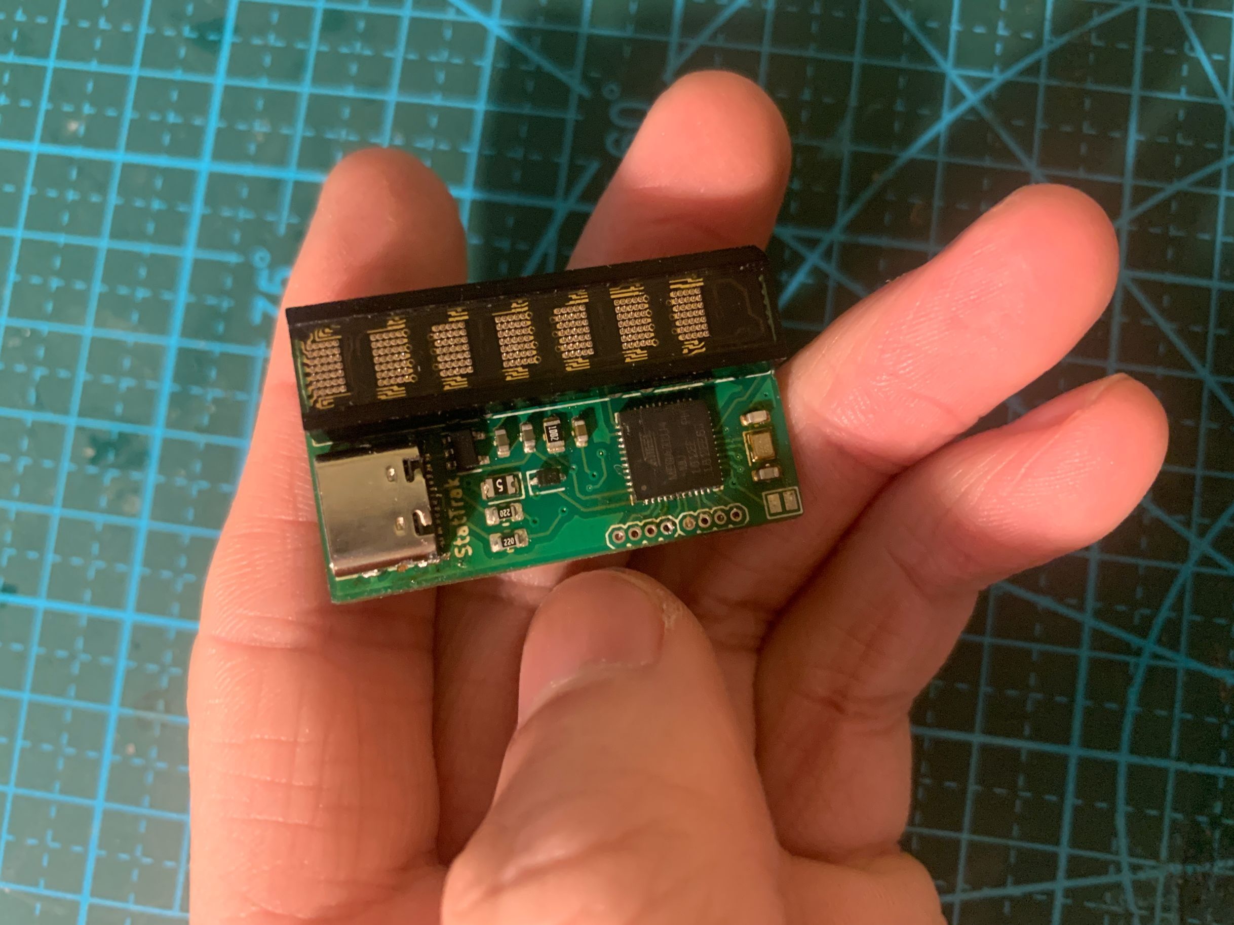
It has to be said that the Type-C interface is more difficult to solder than the QFN44.
Shell design iterations
I was quite satisfied with the internal circuit part of this solution, so I started working on the shell production.
Shell V1: BB style (failed)
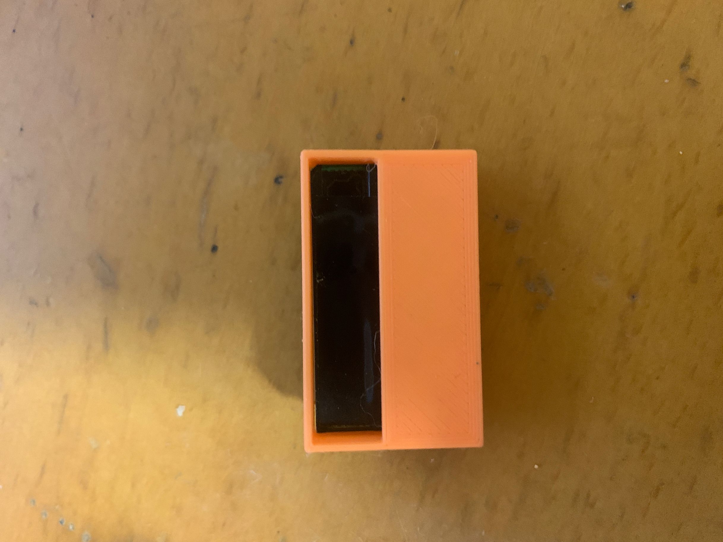
The screen width accounts for half of the overall width. If you add the case directly, it will look like a BB player, or a radio.
Maybe I could put the PCB sideways…
Or just let him have this big chin, I can’t save it…
No, you can’t compromise here! So I was forced to come up with a second plan.
Case V2: ID bezel-less design
Let’s pay tribute to LeTV’s ID Borderless!
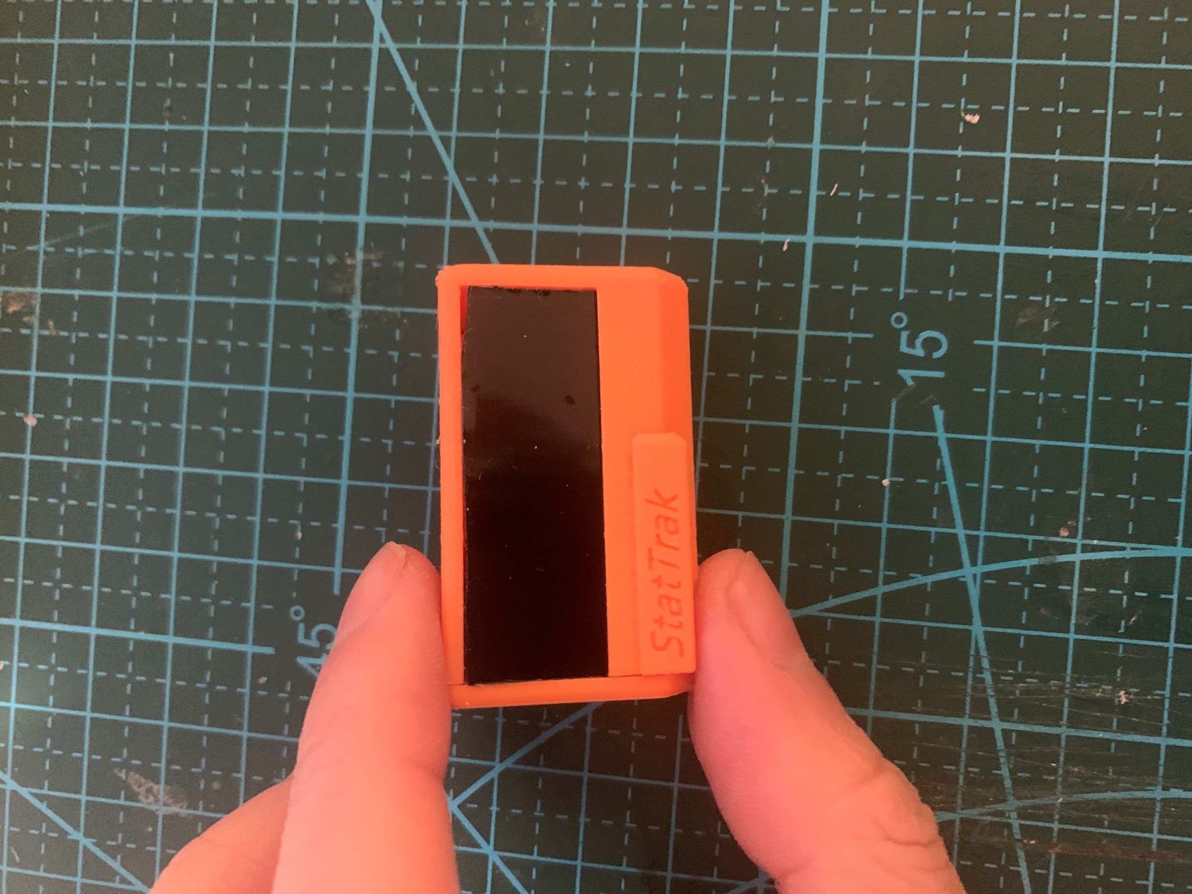
As long as I don’t light up the screen, you’ll never know what my actual display area is.
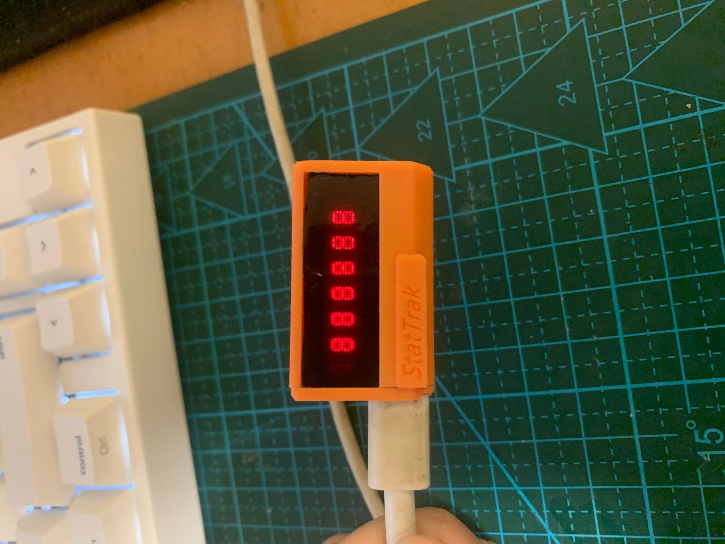
Summary of technical points
| Stage | Pitfalls | Experience and lessons |
|---|---|---|
| Solution 1 | OLED size is too small | Verify the size first and then decide on the solution |
| Solution 2 | Dot matrix screen pin information is wrong | Always measure and verify by yourself, do not blindly trust the seller’s information |
| Solution 2 | The appearance is too rough | The appearance design should be carried out simultaneously with the circuit design |
| Solution 3 | Type-C soldering difficulty | Prepare flux and fine tip soldering iron |
| Solution 3 | The proportion of the shell is out of proportion | Consider visual deception techniques such as “ID without borders” |
Open source project
All design files (schematic diagram, PCB, firmware code) of this project are open source and are welcome for reference and improvement.